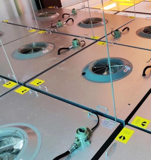
Installation and operation of the clean room FFU, the core of which is to follow the GB51110-2015 specification, ensuring environmental and personnel cleanliness, leveling of the frame, proper sealing, electrical safety, leak detection, and standardized operation, to ensure cleanliness and stable airflow. I. Execution Standards and Basic Requirements 1. Core Specifications GB51110-2015 “Construction and Quality Acceptance Specifications for Clean Rooms” (mandatory) IEST-RP-CC001 (Filter Testing), IEST-RP-CC002 (FFU Performance) 2. Environmental Conditions Temperature: 5–45℃; Relative Humidity: ≤85% (35℃); Air Pressure: 86–106 kPa Installation Area Sealed, Dust-Free, Fresh Air Pre-Purification ≥ 72 hours, Dust Concentration ≤ 3500 particles/L (≥0.5 μm) Floor and Ceiling Load Compliance with Design, Horizontal Deviation of Frame ≤ 2 mm/m 3. Personnel and Materials Personnel: Clean Clothing, Gloves, Dust-Free Shoes, Hair Cover, Prohibition of Bare Hand Contact with Filter Equipment: FFU Appearance without Deformation / Rust / Peeling, HEPA/ULPA without Damage, Sealing Gasket in Good Condition Tools: Dust-Free Cloth, Isopropyl Alcohol, Level, Torque Wrench, Insulated Electrical Tools II. Installation Process (Including Key Control Points) 1. Construction Preparation Review of Drawings: Clearly define FFU layout, quantity, size, air volume (conventional 0.45 m/s ± 20%), speed control method, electrical wiring Site Cleaning: Use dust-free cloth + isopropyl alcohol to wipe the
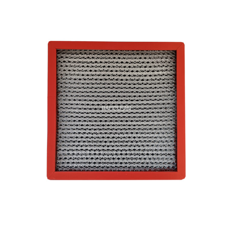
Installation Specifications and Operating Procedures for Clean Room FFU and Precautions I. Pre-construction Preparation Precautions All construction personnel must wear dust-proof suits, masks, head covers, dust-proof gloves, and dust-proof shoes. It is strictly prohibited to touch the FFU cabinet, high-efficiency filter paper, and sealing rubber strips with bare hands. The installation site should be thoroughly cleaned and dusted before construction. Cross-construction (electric welding, cutting, grinding dust operations) is prohibited to avoid dust pollution of the filter element. After unpacking the FFU and high-efficiency filter, handle them gently. It is strictly forbidden to invert, lay flat and heavily press, or bump and drop; the filter must not be placed vertically against the wall for squeezing. Check the model, size, voltage, control method (single control / group control) of the FFU and accessories (sealing rubber strips, suspension rods, bolts, control lines). If any parts are damaged, return and replace immediately. The frame and framework of the clean room should be adjusted and corrected in advance. The horizontal deviation should be ≤ 2mm/m. The ceiling and suspension rods must meet the load of the FFU. It is strictly prohibited to install beyond the load capacity. II. Installation Precautions for FFU The air outlet
The core difference between gas environment explosion-proof FFU and dust environment explosion-proof FFU lies in the completely different explosion-proof standards, sealing protection, temperature control, structural design and certification marks. The two cannot be interchanged. The following is a comparison from key dimensions: 1. Applicable environment and explosion mechanism Gas explosion-proof FFU (Ex d) Applicable: Lithium batteries (electrolyte vapor), pharmaceuticals (ethanol / acetone), chemical industries, etc. environments with flammable gases / vapors. Mechanism: Gas molecules are uniformly mixed, encountering sparks / high temperatures causes instantaneous explosion, and the flame spreads quickly. Dust explosion-proof FFU (Ex tD) Applicable: Aluminum powder, carbon powder, milk powder, cocoa powder, etc. environments with combustible dust. Mechanism: Dust suspends as a “dust cloud” or accumulates, encountering high temperature / sparks ignites, and prone to secondary explosion. 2. Explosion-proof standards and identification (the most distinguishable aspect) Dimension Gas explosion-proof FFU Dust explosion-proof FFU National Standard GB 3836(IEC 60079) GB 12476(IEC 61241) Explosion-proof mark Ex d IIB T4 Gb (Commonly used) Ex tD A21 IP65 T4/T6 Db Temperature category T4(≤135℃)/T6(≤85℃) T4/T6 (More stringent than gas, preventing dust accumulation and spontaneous combustion) III. Structural Design Differences (Core Hardware Differences) 1. Shell and Sealing Gas Explosion-proof: Flameproof type (Ex d), thick
Explosion-proof FFU Intelligent Control System – Core Functions + Practical Advantages Intelligent explosion-proof FFU control system, specifically designed for flammable and explosive clean workshops (lithium battery, pharmaceuticals, chemicals, dust workshops), differs from ordinary manual models. It supports centralized control, variable frequency speed regulation, security linkage, energy saving, and maintenance convenience. 1. Core Functions 1. Zone / Single Unit Variable Speed Control Supports single-unit control, zone control, and whole workshop group control Multiple gears / Variable frequency speed regulation, suitable for different clean area air exchange requirements Settable timed wind speed: high production during the day, low speed during night duty 2. Remote Central Monitoring Equipped with RS485, Modbus, industrial Ethernet Central control computer / touch screen / local panel real-time viewing: operating status, wind speed, current, faults Remote centralized management, no need to manually adjust each unit on-site 3. Automatic Fault Alarm Real-time monitoring and pop-up / sound and light alarm: Fan overload, phase missing, stuck Motor over-temperature, circuit abnormality Communication disconnection, single unit offline 4. Filter Mesh Pressure Difference Monitoring and Lifespan Reminder Equipped with intrinsically safe explosion-proof pressure difference sensor Real-time monitoring of the degree of efficient filter mesh blockage Excessive pressure difference automatically reminds to replace the
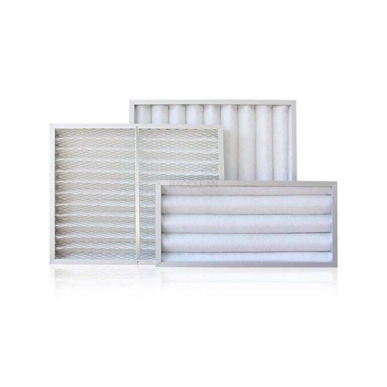
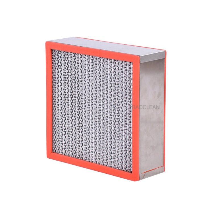
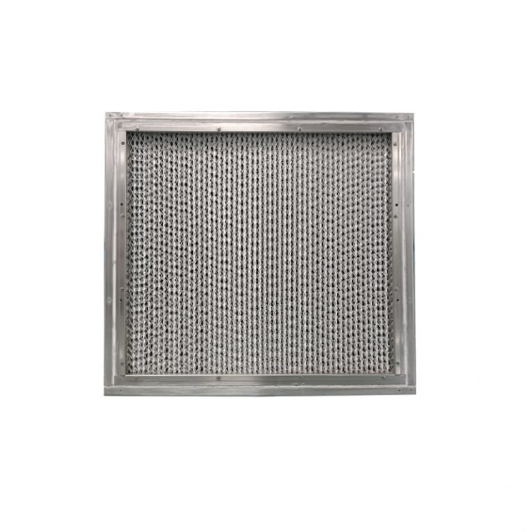
The standard service life of each core component of the laminar flow hood (industry standard, normal clean conditions) 1. Centrifugal fan / Turbulent fan Service life: 8 to 12 years; average daily operation time of about 60,000 to 100,000 hours; dust-free and non-overloaded can last up to 12 years; with large dust and long-term full-load operation will shorten to 6 to 8 years. 2. High-efficiency filter HEPA (end) Service life: 1.5 to 3 years; in a conventional clean workshop: 2 to 3 years; with large dust flow: 1.5 to 2 years; replace based on wind speed decrease and pressure difference exceeding the standard. 3. Intermediate / Primary filter Primary: 6 to 12 months Intermediate: 1 to 2 years Pre-filter material protects HEPA, timely replacement can significantly extend the service life of the high-efficiency filter. 4. Electrical control part (controller, speed regulator, switch, sensor) Service life: 8 to 15 years; ordinary buttons / speed control panel: 8 to 10 years; digital pressure difference, intelligent controller: 10 to 15 years; main aging occurs on the circuit board and button contacts. 5. Box frame (stainless steel / color steel plate / aluminum plate) Service life: 15 to 20 years + 304 stainless steel
Extend the service life of core components of laminar flow hoods. Complete practical methods. (For fans, HEPA filters, primary/middle efficiency filters, electrical control, cabinet, seals, etc., each item is a direct implementation method in the workshop) 1. Extend the lifespan of the fan (target: use for 10–12 years or more) Do not operate at full load and full speed for a long time Operate at medium-low speed daily, do not keep at the highest speed all year round to reduce bearing wear and motor overheating. Replace the pre-filter on time If the primary and middle efficiency filters are clogged, the negative pressure of the fan will increase and the load will soar, which is very likely to burn the motor and damage the bearings. Clean the fan blades regularly Clean the accumulated dust once every six months by cutting off power and avoiding imbalance, vibration and abnormal noise of the blades, and accelerating the damage of the bearings. Avoid frequent start-stop Do not repeatedly switch on and off for a short period of time. Frequent start-stop is the most harmful to the motor coil; intermittent use should be set with constant operation. Implement shock absorption and horizontal installation Install shock-absorbing
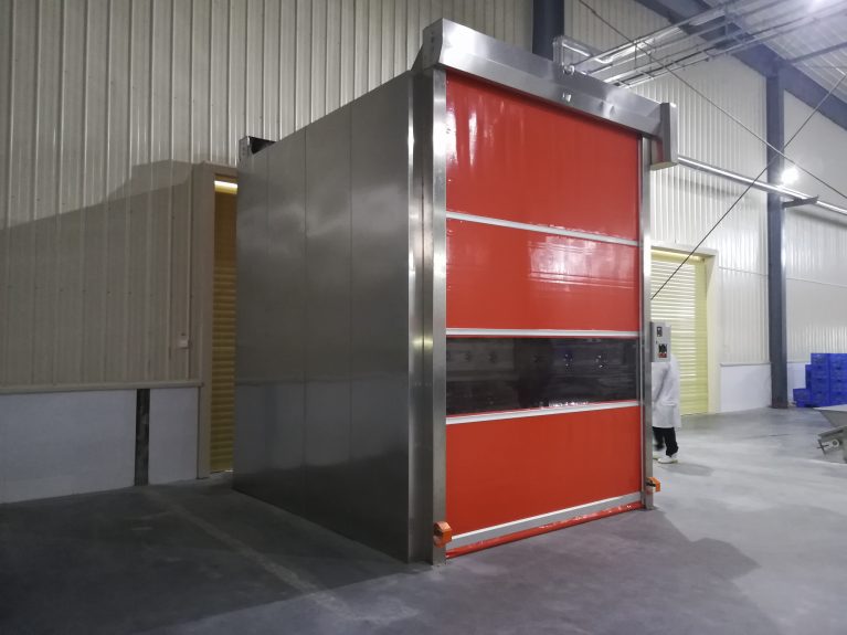
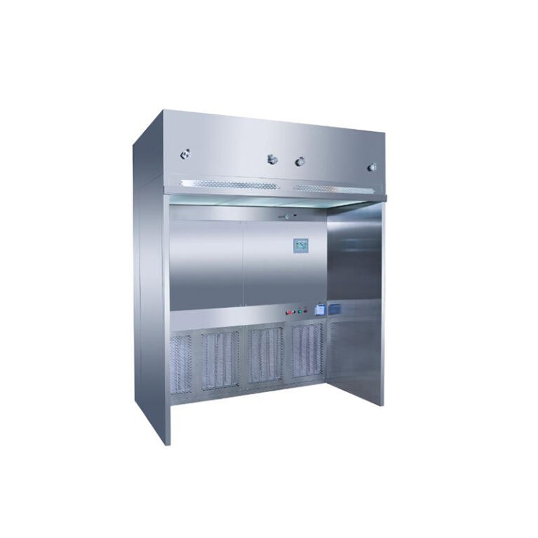
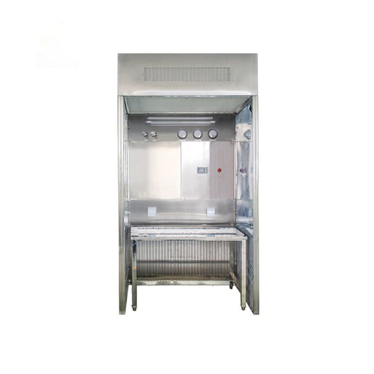
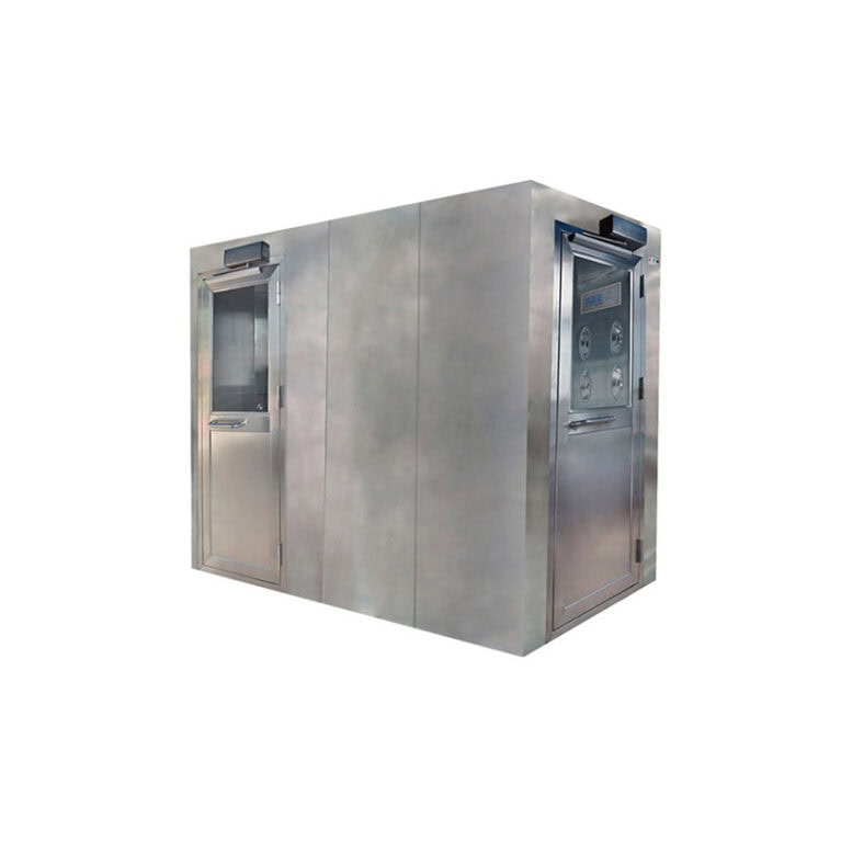
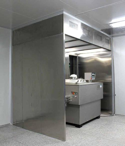
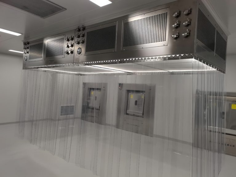
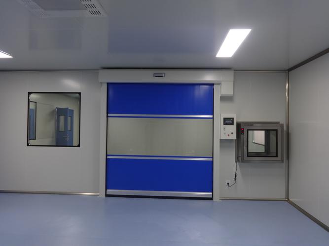
The working principle of the explosion-proof air shower room can be summarized as follows: high-speed clean air flow circulation for dust removal + full-loop explosion-proof electrical and anti-static design + double-door interlocked air lock isolation. It simultaneously achieves personnel purification and inherent safety in flammable and explosive environments. 1. Basic purification principle (the same as ordinary air shower room) Induction and interlock: When personnel enter the air shower room, the explosion-proof infrared sensor detects the position, and the dual-door electronic interlock is activated. The two doors cannot be opened simultaneously, forming an air lock isolation. Air circulation: The explosion-proof centrifugal fan sucks in the indoor air, passing through G4 primary filter (intercepting particles larger than 5 μm) → static pressure box for pressure stabilization → H13/H14 high-efficiency filters (filtering particles of 0.3 μm with an efficiency of ≥ 99.97%). High-speed blowing: Clean air is blown through the multi-angle adjustable nozzles on both sides and the top of the box at a speed of 25–35 m/s, forming a 360° no-corner blowing, removing dust, fibers, and microorganisms from the surface of clothing. Return air filtration: The contaminated air flows back through the bottom return grille and enters the primary / high-efficiency filters
Select explosion-proof air shower cabinets, the core is to first determine the explosion-proof level → then match the purification and size → finally check the material, electrical and certification. Five steps can lock in the compatible model, avoiding both safety and purification risks. 1. First, clearly define the hazardous environment (the explosion-proof level is the lifeline) 1) Hazard zone classification (GB 3836/GB 50058) Zone 0: Continuous presence of flammable gas (rarely used, requires Ex ia intrinsically safe type) Zone 1: May occur during normal operation (mainstream: Ex d IIB T4 flameproof type) Zone 2: Only briefly present during abnormal conditions (optional: Ex d IIB T4 or Ex ec enhanced safety type) 2) Temperature group (T4 is the most commonly used) T4 (≤135℃): Lithium batteries, chemicals, pharmaceuticals (suitable for most solvents / dust) T6 (≤85℃): Highly flammable media (such as ether, ethylene oxide) 3) Typical industry configuration reference Lithium battery workshop (aluminum powder / electrolyte vapor): Ex d IIB T4, 304 stainless steel, anti-static Chemical / pharmaceutical (organic solvents): Ex d IIB T4, 316 stainless steel, corrosion-resistant Spraying / ink (paint mist / solvent): Ex d IIB T4, anti-static nozzle, spark-free fan 2. Match purification level and air shower performance 1)
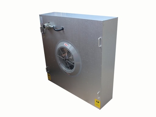
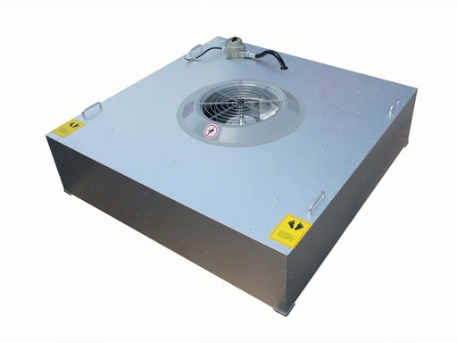
The complete working principle of explosion-proof FFU (easy-to-understand + professional version) I. Overall Definition Explosion-proof FFU = Explosion-proof sealed motor + centrifugal fan + efficient filter + explosion-proof electrical sealing structure that combines local air circulation purification + explosion-proof flame retardancy and elimination of ignition sources as the two core functions. II. Basic purification working principle (consistent with ordinary FFU) Negative pressure intake The fan rotates at high speed, sucking in the workshop air from the top; Positive pressure supply The centrifugal fan generates static pressure, evenly pushing the air downward; Efficient filtration The airflow passes through HEPA/ULPA efficient filters, filtering dust and particles; Laminar air supply The clean air is sent downward in a uniform laminar flow, maintaining the pressure difference and cleanliness of the clean room / explosion-proof clean area. III. Core: Explosion-proof principle (key difference) This is the core part of explosion-proof FFU, used to prevent flammable and explosive gases, solvent vapors, and combustible dust from being ignited. 1. Motor explosion-proof isolation A flameproof / enhanced safety type explosion-proof motor is used, with the motor stator, coil, and wiring chamber being fully enclosed explosion-proof cavities; Even if there is a short circuit, sparking, or generation of electric
Explosion-proof FFU standard maintenance cycle (industry standard + lithium battery / chemical / pharmaceutical explosion-proof scenarios) Based on explosion-proof regulations + cleanroom operation + annual explosion-proof electrical inspection requirements, the cycle is clearly defined in four major items and directly implemented. 1. Daily inspection (daily) Check for abnormal sounds, vibrations, excessive heat, and odors Check for any loosening or cracking of explosion-proof junction boxes, shells, and seals Check the grounding of the machine body and the integrity of the equipotential connection lines Applicable: All explosion-proof FFUs, mandatory 2. Routine maintenance (monthly) Clean the FFU body and floating dust in the intake ports Tighten explosion-proof screws, connection terminals, and explosion-proof sealing joints of cables Check the pressure difference of the filter, and the uniformity of the air outlet Check the temperature rise of the motor and whether the operating current is normal 3. Mid-term maintenance (every 3 to 6 months) 1. Filter replacement General explosion-proof clean areas: about 6 months Lithium battery / chemical / high solvent, high dust environment: about 3 months Based on the pressure difference value: replace immediately if the resistance exceeds the standard (prioritize checking the pressure difference, not strictly adhering to the time limit) 2. Fan
Explosion-proof FFU Installation + Maintenance Complete Set of Precautions (Industry Practical Version) I. Installation Precautions 1. Preliminary Selection and Environmental Matching Select according to the actual explosion-proof area level (Ex d IIB/IIC T4/T6, gas / dust explosion-proof classification), and strictly prohibit using ordinary FFU to replace explosion-proof units. Confirm the temperature and humidity, corrosive gases, and concentration of flammable and explosive vapors on site, and match with anti-corrosion and anti-static models. Verify the load-bearing capacity of the clean room ceiling, as the explosion-proof FFU is heavier, the brackets and ceiling frame must be reinforced. 2. Electrical Installation (Explosion-proof Core) Use explosion-proof conduit, explosion-proof junction boxes, and sealed joints for electrical wiring. Ensure the sealing of interface fillers is compact to prevent combustible gas from entering the cavity. Must perform reliable grounding and equip potential equalization connections. Connect the entire machine, frame, and metal parts of the ceiling to eliminate static accumulation. Do not privately modify or connect power lines; the wiring must be firmly pressed to prevent short circuits and sparking; switches and controllers must be of explosion-proof type. Use explosion-proof frequency converters / explosion-proof control modules for variable frequency control. Ordinary speed regulators are prohibited from use in explosion-proof
Explosion-proof FFU (Explosion-proof Fan Filter Unit) is mainly used in places where there is a risk of fire and explosion and where high cleanliness standards are required. Its core lies in simultaneously meeting the two demands of “explosion-proof safety” and “air purification”. I. Electronics / Semiconductor and Display Industry Semiconductor manufacturing: Chip fabrication, lithography / etching workshops, wafer clean rooms (organic solvents / silane flammable). Optoelectronic display: LCD/OLED panels, backlight modules, optical lens workshops (ink / solvent evaporation). Precision electronics: Hard drives / magnetic heads, micro-motors, sensor assembly (anti-static + explosion-proof). II. New Energy and Battery Industry Lithium battery manufacturing: Cathode and anode coating, injection, formation workshops (electrolyte vapor flammable). Energy storage / hydrogen: Energy storage stations, fuel cell workshops, hydrogen production area (hydrogen explosion-proof). III. Medicine and Biochemical Engineering Pharmaceutical workshops: Sterile raw materials, organic solvent crystallization / drying areas, explosion-proof clean sheds (ethanol / acetone etc.). Biological preparations: Fermentation tank areas, sterile sampling, biosafety laboratories (BSL-3/4). Fine chemicals: Explosion-proof clean reaction areas, powder feeding / mixing (combustible dust). IV. Food / Cosmetics and Powder Industry Food processing: Milk powder / cocoa powder production, sterile filling lines (starch / milk powder dust explosion-proof). Cosmetics: Perfume / perfume formulation, powder