Passage Window Complete Usage Prohibitions (General for Cleanrooms, divided into four categories: operation, materials, equipment, and safety) I. Door Interlock Operation Prohibitions (The most critical, directly disrupting the clean air pressure difference) It is strictly prohibited to open both the inner and outer doors simultaneously. The interlock device is designed to prevent both doors from opening at the same time. Once both doors are opened simultaneously, the positive pressure in the clean area will be lost, and dust and microorganisms from the outside will directly flow in, causing the entire clean room to be contaminated; if the interlock fails, it must be immediately stopped and repaired. It is forbidden to forcibly pry the door open or dismantle the interlock switch. It is prohibited to open one door while the other is not fully closed. If the door is not tightly fastened or there is a gap in the sealing strip, the pressure difference will continue to leak, equivalent to a partially open door causing contamination. Do not lean against, collide with, or forcefully drop or smash the passage window door. This may cause the door frame to deform, the sealing strip to not be tightly pressed, and the electromagnetic lock
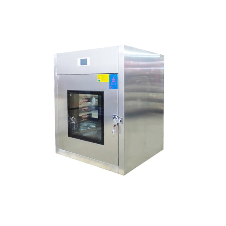
Common disinfection methods, applicable scenarios and operation points of transfer windows They are divided into three categories: daily physical disinfection, chemical wiping disinfection, and space fumigation sterilization. They are used separately in ordinary clean workshops and sterile/biological workshops. 1. Ultraviolet disinfection (standard equipment, most transfer windows are equipped with it) Applicable: Daily disinfection of material surfaces and interior of the box, standard for electronic interlock transfer windows Principle: Short-wave UV-C damages the DNA of microorganisms, killing bacteria, molds and viruses Operation guidelines Do not block the lamp tube when placing materials, turn on the ultraviolet lamp after closing the door; In the ordinary clean area, the irradiation time is ≥ 15 minutes, in the sterile workshop ≥ 30 minutes; After the irradiation is completed, turn off the ultraviolet lamp, and wait for 2-3 minutes before opening the door. Notes for Attention When the ultraviolet light is on, do not touch or look directly at the lamp tube; If the lamp tube accumulates dust, it will significantly reduce the sterilization effect. Clean it weekly; After a cumulative usage of 800 hours, the lamp tube must be replaced. The irradiation intensity must be lower than 50μW/cm² for failure. Limitations: There are shadow
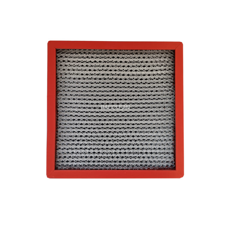
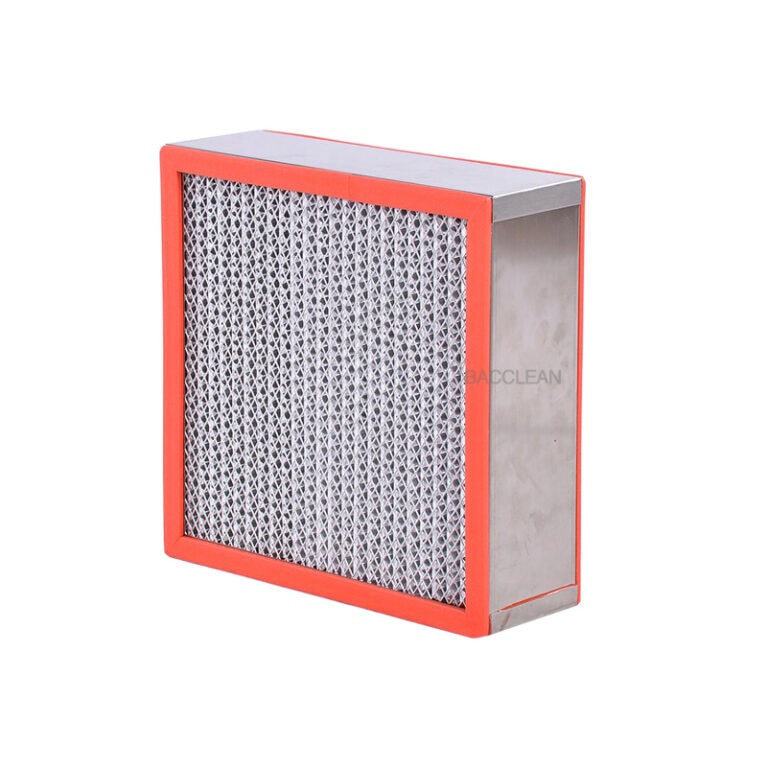
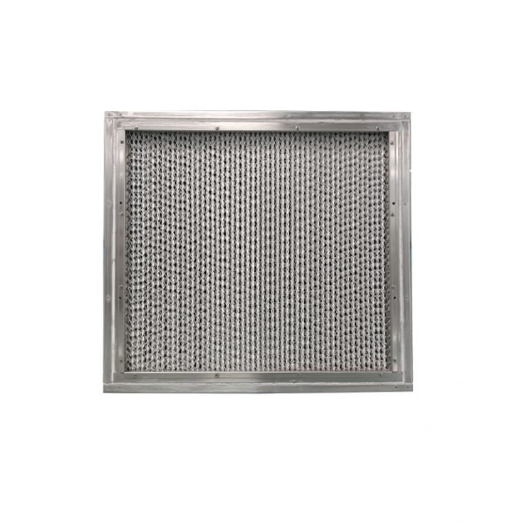
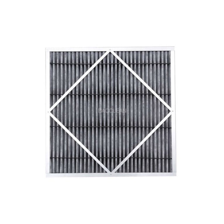
Based on on-site practical operations, it is divided into three parts: core determination basis, intuitive appearance judgment, and auxiliary condition determination, and ranked by priority. It can be directly used for on-site inspections: 1. Primary determination: Pressure difference resistance (the most authoritative, industry standard) Record the initial resistance of the filter element (the stable pressure difference after the new filter element is installed and running normally, usually 180-220 Pa). When the running resistance reaches twice the initial resistance, it must be replaced. If the pressure difference rises rapidly in a short period of time, it indicates that the filter element is severely clogged / damp, and it should be replaced in advance. 2. Intuitive appearance & seal check (can be checked with the naked eye) Filter material body: Large areas of blackening on the surface, heavy dust accumulation, holes, cracks, and loose fibers, immediately replace. Damp / moldy: Water stains, mold spots, and odors on the filter material and frame, directly replace (the filter material’s filtration efficiency will permanently decrease after getting damp). Sealing part: Failure of the sealing strip between the filter element and the frame, filter element deviation, repeated adjustments still leak air, replace the filter element and
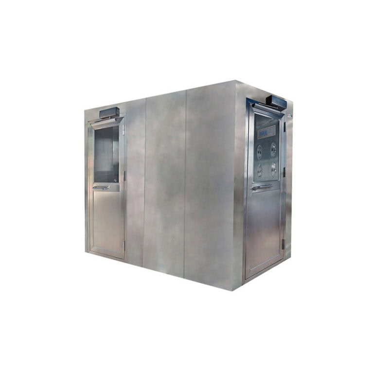
Pass box maintenance cycle (General Industry Standard for Cleanrooms) Divided into daily, weekly, monthly, quarterly, and annual categories, it distinguishes between ordinary ultraviolet pass boxes and laminar flow air shower pass boxes, adapting to the general specifications of pharmaceutical enterprises and electronic cleanrooms. 1. Daily maintenance (per shift / before and after shift each day) Clean the inner walls, glass, countertop, and sealing strip surfaces of the box with 75% alcohol for disinfection; Check if the double doors are closed tightly and if there are any gaps; Test if the interlock indicator light, lighting lamp, and ultraviolet lamp can be turned on normally; Clear the box of debris, water accumulation, and stains. Applicable to all types of pass boxes, it must be done after each shift operation. 2. Weekly maintenance Fully disassemble the sealing strip, clean the accumulated dust in the gaps, and dry and reset; Wipe the door frame, door lock, and electromagnetic lock contact surfaces of dust; Check the dust on the surface of the ultraviolet lamp tube and wipe it with a dust-free cloth; Laminar flow type: Clean the surface of the primary filter screen. 3. Monthly maintenance (monthly inspection and maintenance) Clean and lubricate the mechanical/electronic
Based on the working conditions and environmental conditions, classify them according to the length of service life, and mark the changes in resistance, replacement cycle, and influencing reasons, to adapt to on-site management: 1. High cleanliness level + Excellent environment (optimal working condition) Applicable scenarios: Pharmaceutical sterile areas, precision electronic dust-free workshops, biological safety laboratories, full fresh air + pre-filtering complete Environmental characteristics: Few dust particles, stable temperature and humidity, no odor / water vapor / corrosive gases, complete front-end primary / intermediate filtration Service life: 10 to 12 months Features: Slow pressure increase, clean filter element appearance, rarely occurs moisture absorption, mold problems. 2. Conventional industrial clean area (standard working condition) Applicable scenarios: Ordinary purification workshops, food packaging workshops, regular laboratories Environmental characteristics: Small amount of dust production, normal temperature and humidity, complete front-end filtration configuration, intermittent / continuous operation Service life: 6 to 9 months Features: Resistance rises uniformly, inspection according to cycle is sufficient, it is the most common working condition. 3. High dust / dust-producing environment (shortened service life) Applicable scenarios: Powder feeding, weighing, grinding, batching workshops, raw material processing areas Environmental characteristics: High particle content in the air, heavy front-end filtration load Service life: 3
Based on the working conditions, pressure difference standards, and industry scenarios, provide the regular service life for each scenario. Also, distinguish between theoretical duration and actual usage duration, and mark the special requirements for explosion-proof areas: I. General determination criteria The initial resistance is set at 120-180 Pa, and the termination replacement resistance is 300-350 Pa. Explosion-proof areas should prioritize pressure difference, while the time is only for reference. II. Service life by scenario Low dust and clean explosion-proof areas (pharmaceutical sterile areas, precision optics, ordinary explosion-proof laboratories) With little environmental dust, oil mist, and solvents, continuous operation for 24 hours: 5-8 months; intermittent operation can reach 8-12 months. Medium pollution explosion-proof areas (electronic explosion-proof workshops, some fine chemical industries) A small amount of organic solvents and slight dust: regular 3-5 months. High pollution explosion-proof areas (lithium battery production, electrolyte/solvent workshops, cosmetics filling, oil mist/flammable dust conditions) Pollutants are prone to adhere and penetrate the filter material, and the resistance increases rapidly: 2-3 months, and in some heavy oil-soiled environments, it may even be less than 2 months. III. Additional influencing factors Installing primary / pre-filter screens: The overall service life can be extended by 30% to 50%, which is
Based on the operating conditions and industry standard practices, the recommended replacement periods are provided for different scenarios, along with the basis for the determination (the time is only for reference; priority should be given to the pressure difference / wind speed): 1. Standard Replacement Period Continuous operation for 24 hours Conventional clean area: 1.5 – 2 years Areas with slight dust generation / large flow of people: 1 – 1.5 years Daily intermittent operation for 8 – 12 hours Conventional clean area: 2 – 3 years Aseptic / low-dust areas: up to 3 years + 2. Supplementary Comparison (Combined with Pre-filter) For initial / medium-efficiency filters, maintenance according to the upper limit period and environmental cleanliness: Execute according to the upper limit period If the pre-filter exceeds the service life or there is a lot of dust on site: Follow the lower limit period or replace earlier 3. Important Reminder The time is only a reference and should not be the sole basis When the pressure difference reaches twice the initial value, the wind speed does not meet the standard, or the leak detection of PAO/DOP is不合格, regardless of whether it is the replacement period or not, replace immediately.
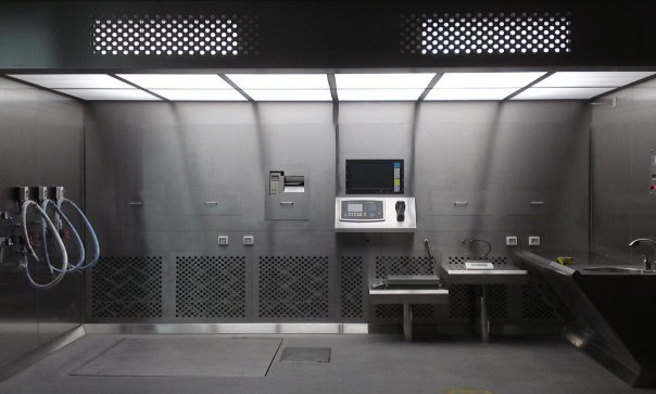
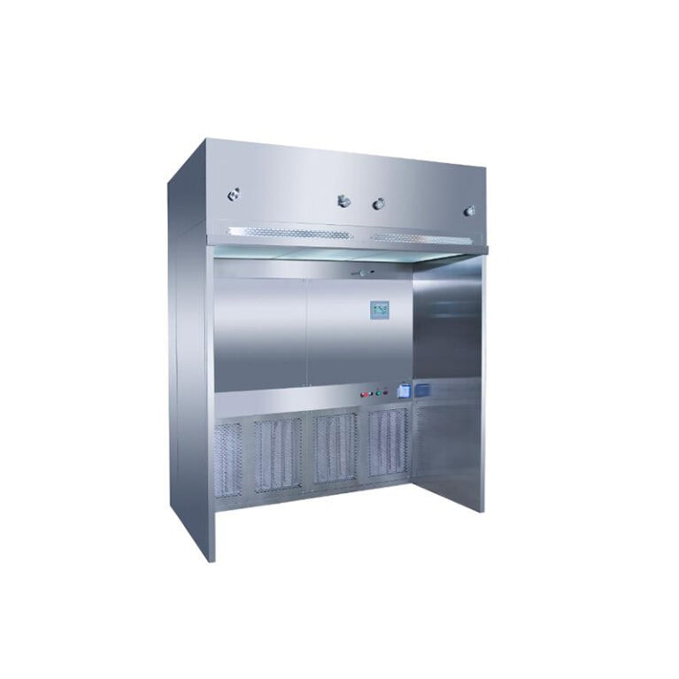
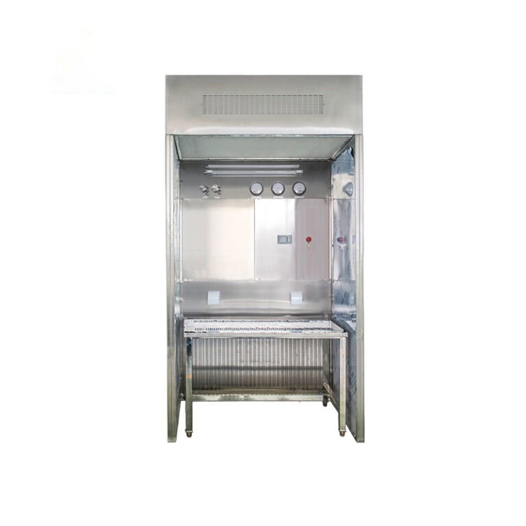
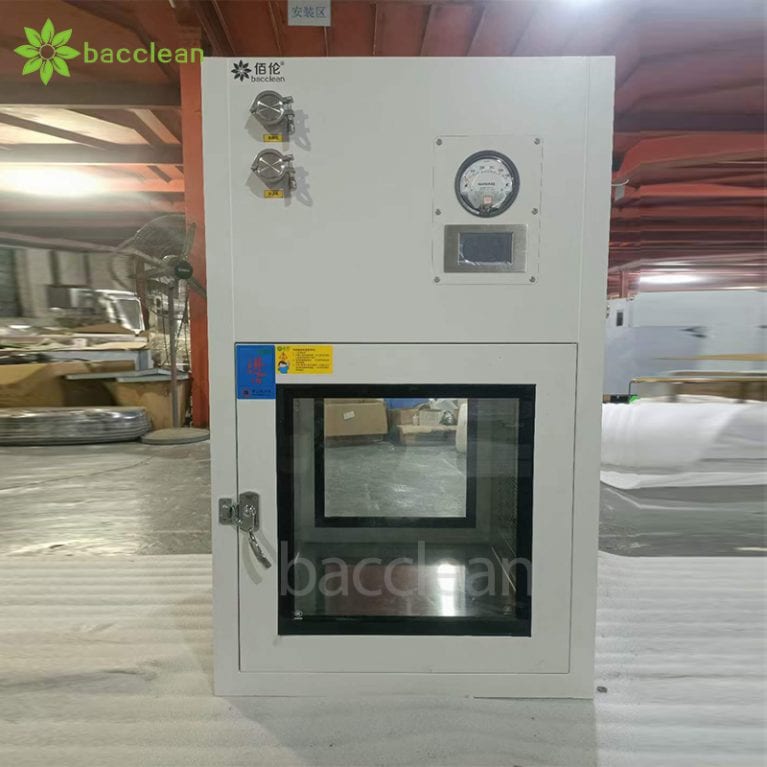
The core of daily maintenance for the negative pressure weighing chamber is as follows: daily cleaning + parameter inspection, weekly deep cleaning and seal check, monthly filter and duct maintenance, annual leak detection and calibration. The entire process follows GMP to ensure stable negative pressure, compliant airflow, and no cross-contamination. 1. Daily Maintenance (per shift / per day) 1. Before startup check Negative pressure value: The differential pressure gauge shows **-15 to -30 Pa**, stable without fluctuations. Working surface wind speed: 0.35 to 0.45 m/s, no turbulence. Function status: Fan, lighting, alarm are normal, no abnormal noise, no air leakage. Appearance cleanliness: Inner walls, tabletop, return air vents, operation ports have no dust or residual materials. 2. Cleaning and disinfection (must be done after operation) Power off protection: Turn off power and ventilation, wear gloves, protective clothing, and mask. Remove residues: Use dust-free tools to remove residual materials on the tabletop to avoid touching the materials. Surface wiping: Dip a dust-free cloth in purified water / 75% ethanol, wipe the tabletop, side walls, and door body from top to bottom, from inside to outside in a single direction; use cotton swabs to clean the gaps. Disinfection: Secondary wipe with 75%
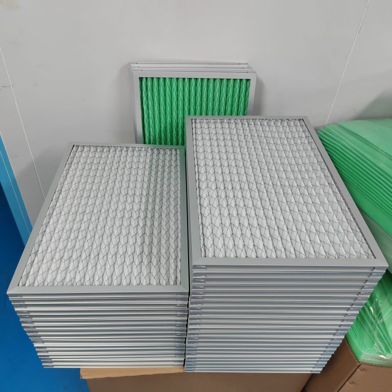
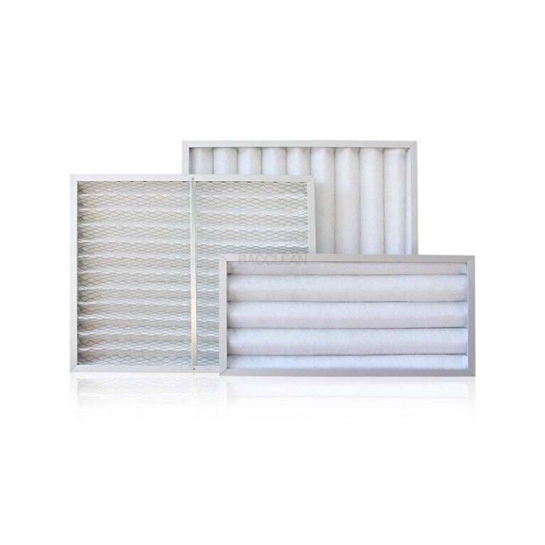
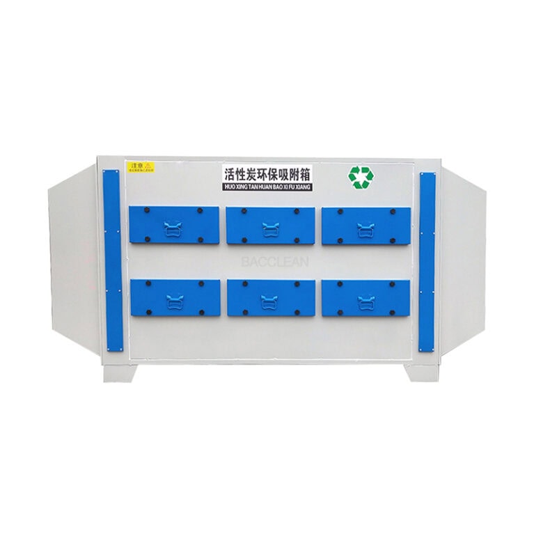
As medium-efficiency filters, they are mainly applied in humid, high airflow and dusty environments, such as in the pharmaceutical and food manufacturing industries. As the front-end filtering part of the filtration equipment, they have a fast filtration speed and a large dust-holding area, which can effectively save energy and extend the service life of the equipment. Therefore, the medium-bag type filters are highly favored by customers. The specific advantages of using Changri air filter manufacturer are explained to you one by one: What are the characteristics of the replacement cycle for medium-efficiency bag filters? Judging whether a replacement is necessary can be done simply by observing the dust accumulation on the surface. Generally, the wind speed of medium-efficiency filters is lower than that of primary filters, and it is difficult to feel the air flow condition by hand. In actual maintenance, people prefer to replace the primary and medium-efficiency filters together, which is not wasteful and also avoids the trouble of frequently entering the air conditioning cabinet. If the air containing dust collected by the air conditioning cabinet is particularly heavy, the primary filter can be replaced to protect the medium-efficiency filter. After all, the cost of the medium-efficiency filter
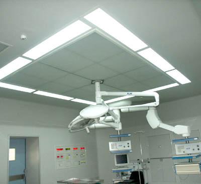
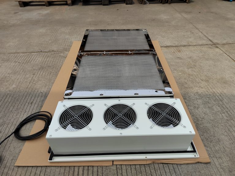
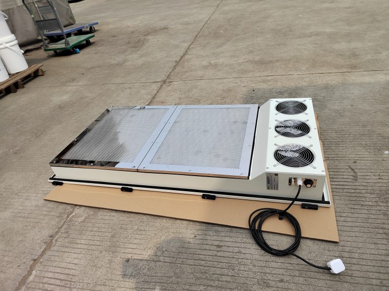
Air supply ceiling ( laminar air supply ceiling ) air supply principle The overall design is static pressure equalization + high-efficiency filtration + unidirectional laminar air supply. The core is to transform the chaotic airflow into uniform and stable unidirectional clean airflow, achieving a local high-clean area. 1. Complete airflow process Air enters the static pressure box The fresh air / recirculating air from the system is sent to the static pressure box of the air supply ceiling. The large cavity slows down the high-speed airflow, stabilizes the pressure, eliminates vortex and uneven wind pressure, and forms a uniform static pressure inside the box. Pre-filtration + medium-efficiency filtration The airflow passes through the primary and medium-efficiency filters first, intercepting large particles of dust, protecting the rear-end high-efficiency filter. High-efficiency filtration The airflow passes through the HEPA/ULPA high-efficiency filter, trapping micrometer and sub-micrometer particles, completing deep air purification. Equalization and rectification The airflow after high-efficiency filtration is further dispersed and homogenized through the equalization plate / orifice plate / equalization membrane, eliminating local wind speed differences and ensuring uniform wind speed across the entire air outlet surface. Unidirectional laminar air supply Finally, the airflow is sent downward at a constant speed
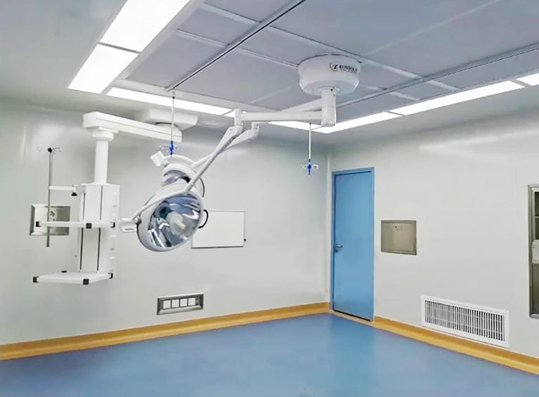
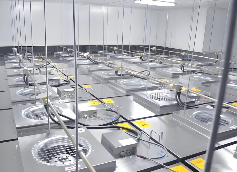
Ceiling Fan Air Supply vs. Ordinary Air Inlets: Principles & Core Differences I. Core Differences in Air Supply Principles 1. Ceiling Fan Air Supply (Laminar Flow Type) Process: Collecting air and stabilizing pressure → Multiple-stage filtration → Rectification and uniform flow → Vertical Unidirectional Laminar Flow The air first enters a large volume static pressure chamber, where the high-speed air slows down and the overall pressure is balanced, completely eliminating turbulence; Then it passes through primary / intermediate / high-efficiency filters for deep purification; Next, it is further rectified by orifice plates and uniform flow membranes, ensuring uniform wind speed across the entire surface; The air flows downward in a low-speed vertical laminar flow (0.30 – 0.45 m/s) in a parallel manner, with no cross-flow or swirling. 2. Ordinary Air Inlets (Blade / Diffuser Inlets) Process: Direct air discharge → Turbulent diffusion There is no independent static pressure chamber. The air flow directly reaches the inlet through the duct, and the distribution of wind pressure and speed is uneven; Mostly equipped with simple filters or no high-efficiency filtration, the purification capacity is weak; The wind direction is changed by blades and diffuser plates, and the air flow presents a chaotic
Based on the safety requirements of explosion-proof scenarios and the key points of filter material protection, it is divided into four parts: pre-filtering, daily management, operation maintenance, and environmental management, taking into account both lifespan and explosion-proof safety: 1. Add pre-filtering to reduce load at the source Install primary + secondary filters in the fresh air system of the workshop to intercept large particles, sludge, and oil mist, avoiding direct blockage of the high-efficiency filter. Additional dust-proof screens / pre-filtering nets can be installed at the FFU inlet, which can be cleaned and replaced regularly to significantly reduce the burden on the HEPA. For areas with oil mist and solvent evaporation such as lithium batteries, chemical plants, and cosmetics, pre-treatment devices for oil removal and dehumidification should be provided to prevent oil contamination of the filter material and irreversible blockage. 2. Standardize operating parameters to avoid overload and accelerate aging Run at the designed air velocity, prohibit long-term full-load overclocking. The higher the air velocity, the faster the resistance of the filter material increases and the shorter its lifespan. Ensure smooth airflow of the unit: do not stack materials or block the inlet/outlet, avoid local vortices and dust accumulation. Arrange