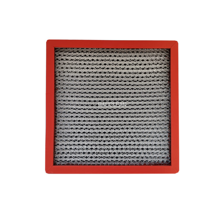
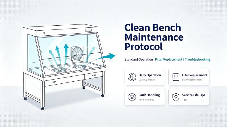
I. Daily Correct Operating Procedures 1. Start the machine for self-cleaning for 10-15 minutes before conducting experiments. 2. Conduct ultraviolet sterilization for 30 minutes before operation. 3. Do not place items at the air outlet or block the airflow. 4. Do not directly pour liquids onto the work surface. 5. Regularly clean the glass and interior to maintain dust-free conditions. II. Filter Replacement Cycle (Industry Standard) Primary Filter: 3 months. It blocks large particles and hair dust and can be used for dust cleaning. Replace it when it expires. High Efficiency Filter: 12-18 months. The core filtering component, not washable. When the pressure difference increases or the wind speed decreases, it must be replaced. III. Common Faults and Solutions 1. Wind speed decreases, purification is weak Reason: Blockage of primary / high efficiency. Solution: Clean the primary filter, check the pressure difference, and replace the high efficiency filter. 2. Cleanliness does not meet standards, experiments are contaminated Reason: Airflow turbulence, leakage of high efficiency, aging of sealing ring. Solution: Check the seal, re-inspect for leaks, and replace the filter. 3. Fan makes abnormal noise, vibration is large Reason: Dust accumulation on the fan, aging of bearings, loose installation. Solution: Clean
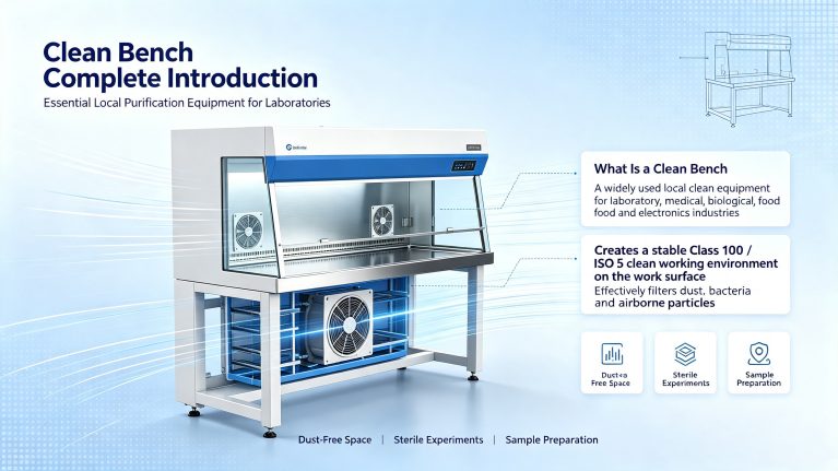
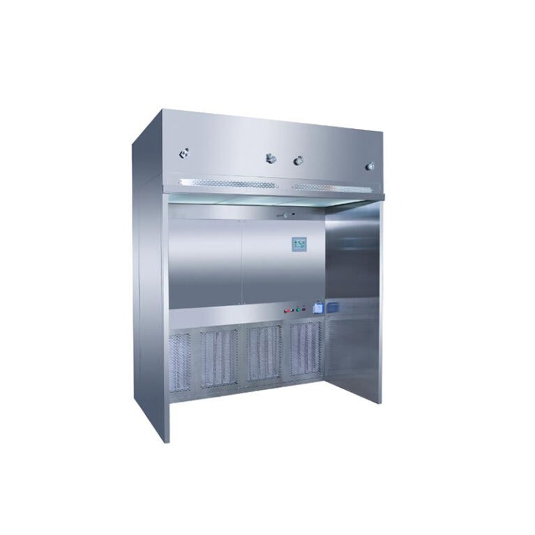
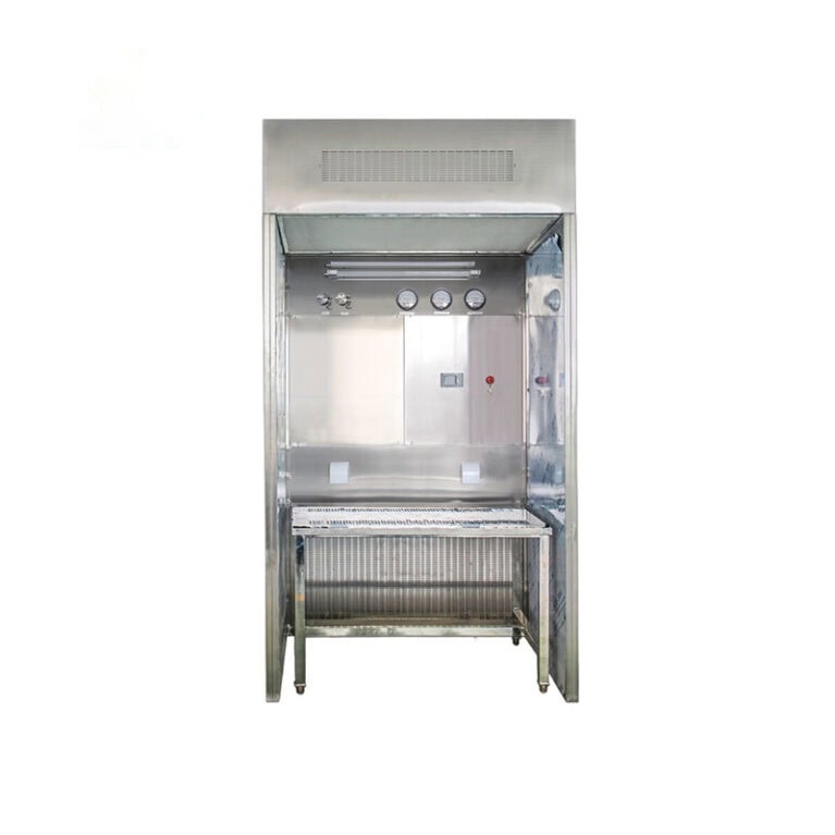
I. Overview of Clean Bench The Clean Bench is the most commonly used single-person/double-person local clean equipment in laboratories, medical fields, biology, food, electronics industries. The equipment forms a stable 100-level (ISO5) clean operating environment on the countertop through built-in fans and multi-stage filtration systems. It can effectively filter dust, bacteria, and particles in the air, providing a dust-free and sterile operating space for precise operations, aseptic experiments, and sample preparation. Compared to laminar flow hoods and clean enclosures, the Clean Bench is smaller in size, plug-and-play, has a lower price, and does not require the renovation of the workshop. It is the preferred equipment for lightweight local purification. II. Working Principle The indoor air is sucked into the cabinet by the fan, pre-filtered by the G4 primary filter, and then purified by the HEPA high-efficiency filter at the end. The air is evenly sent out in parallel laminar flow through the equalizing membrane. The single-direction laminar airflow continuously replaces the air on the countertop, preventing external pollutants from entering the working area, and maintaining the ISO5 level of cleanliness in the operation area for a long time. Standard air velocity: 0.35–0.55m/s Cleanliness level: 100-level (Class 100 / ISO5) III.
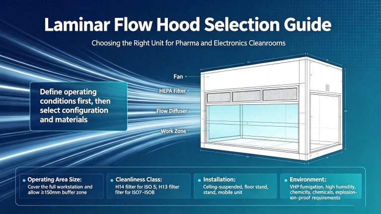
Many projects encounter selection mistakes during the procurement stage of laminar flow hoods, resulting in unmet cleanliness standards, failure to pass GMP inspections, excessive energy consumption, and frequent malfunctions. This article summarizes the complete selection dimensions, covering process requirements, parameters, materials, and configuration comparisons.
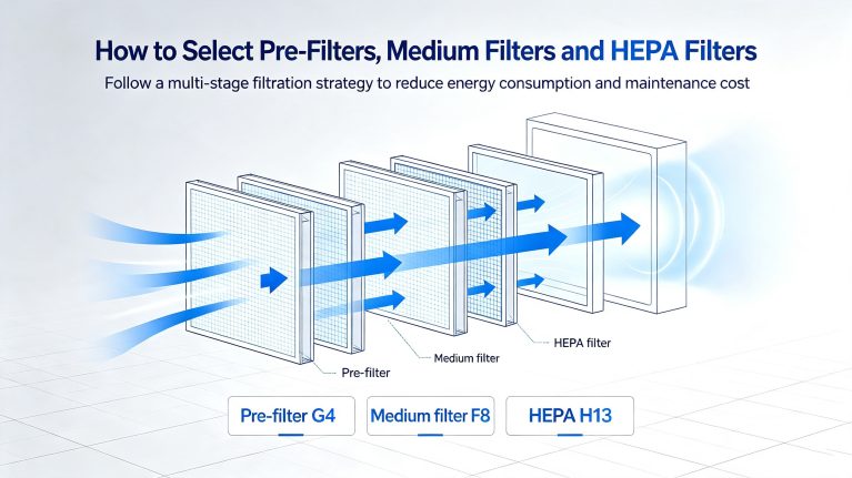
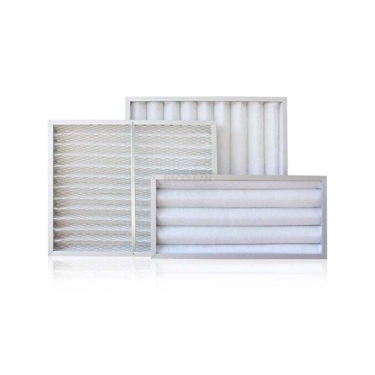
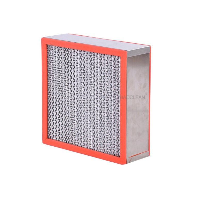
Initial, medium, and high-efficiency filters are not necessarily better the higher their rating. Selection should be based on a comprehensive evaluation of cleanroom class, air pollutant types, airflow volume, pressure drop requirements, site conditions, maintenance budget, and relevant standards (e.g., GMP/ISO14644). Following the core principle of staged filtration—coarse filtration first, fine filtration later—the front-end filter protects downstream precision filters, ensuring compliance with purification standards while controlling fan energy consumption and filter replacement costs. I. Before Selection: Clarify 8 Fundamental Parameters (Prerequisites for Selection) Before selecting a filter, gather essential site information; missing parameters can lead to incorrect model selection: – System airflow: Rated airflow of air handling units, FFUs, or fresh air units (m³/h); actual filter airflow must not exceed rated capacity, as excessive airflow increases resistance and reduces efficiency. – Allowable pressure drop range: Fan static pressure margin; prioritize low-resistance filters to save electricity long-term. – Target cleanliness level: ISO5–ISO9 cleanrooms, general ventilation, operating rooms, laboratories, exhaust gas treatment, etc. – Pollutant characteristics: Dust, fibers, cooking fumes, moisture, mold, chemical aerosols; presence of high temperature, high humidity, or corrosive gases. – Installation space dimensions: Filter frame external dimensions and frame type (bag-type, panel-type, liquid-seal, pleated). – Differential pressure monitoring:
I. Basic Lifespan of Main Two Types of Sensors 1. Electrochemical Sensor (standard in domestic transfer cabinets, low cost) Normal operating conditions (1-3 sterilizations per day, each 30-60 minutes): 12-24 months (1-2 years) – mandatory replacement. High-load conditions (≥5 sterilizations per day, long-term high-concentration VHP immersion): 8-12 months – significant sensitivity decline. Principle shortcoming: H₂O₂ strong oxidizing property continuously consumes the electrolyte and corrodes the electrode, belonging to consumable type. 2. PEROXCAP / Optical TDLAS High-end Sensor (Vaisala, Thermo Fisher high-end models) PEROXCAP film sensing (import high-end probe) Light load (1-2 times per day): 3-5 years; High-load frequent sterilization: 2-3 years; Unique sensor vitality value determination: vitality ≤ 40% – must be replaced, not simply based on years. TDLAS laser optical sensor No electrolyte, corrosion-resistant, theoretical lifespan 3-5 years, almost no consumable loss, only annual calibration required. II. Industry Mandatory Replacement Determination Rules (GMP Compliance, Prior to Fixed Lifespan) 1. Time-based Mandatory Replacement Bottom Line (Recommended in workshop SOP) Economical electrochemical probe: Must be replaced after 2 years, regardless of whether it can still read; Import PEROXCAP probe: Must be replaced after 4 years. 2. Immediate Replacement upon Performance Failure (any one of the following, not waiting for years) Monthly
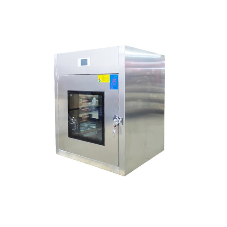
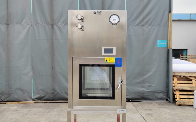
Applicable Scenarios: Aseptic Pharmaceuticals, Biological Laboratories, Cell Rooms, Clean Workshops VHP Hydrogen Peroxide Vaporization Pass Box, covers all-cycle maintenance including cleaning, inspection, consumable replacement, calibration, verification, prohibitions and fault handling after each use, daily, weekly, monthly, quarterly, and annual, and can be directly converted into workshop SOP documents. I. Basic Cleaning Specifications (General for All Cycles) 1. Cleaning Consumables Requirements Cleaning Tools: 300gsm or above dust-free ultra-fine fabric, no loose fibers Disinfectant: 75% Ethanol / 70% Isopropyl Alcohol, rotate every half month to avoid microbial resistance Rinsing Medium: Purified Water, strictly prohibit tap water Prohibited Items: Chlorine-containing disinfectants, steel wool, sandpaper, strong acids and strong bases, abrasive cleaning agents (corroding 316L stainless steel, silicone sealing strips, sensor probes) 2. Cleaning after Each Use (Must Do) Remove materials, clean debris in the chamber, debris, dust; Dust-free cloth dipped in 75% Ethanol wipe the inner walls, tabletop, door handles, observation glass, control panel; Focus on wiping temperature and humidity sensors and probe, remove hydrogen peroxide crystallization (crystallization will cause monitoring data distortion); Wipe the groove of the sealing strip, the air outlet, the surface of the atomization nozzle; Dry all contact surfaces with dust-free cloth, no water accumulation or residual condensation in
With the acceleration of the industrialization of cell and gene therapy (CGT), the expansion of domestic semiconductor production lines, and the wave of new construction and renovation of high-level biosafety laboratories, the standardized general transfer windows have been unable to meet the strict compliance, process, and safety requirements of the specialized fields. The demand for laminar transfer windows with scene-specific customization capabilities has rapidly grown, becoming a core essential equipment in the clean engineering field. I. Decomposition of Diverse Customization Needs in Three Core R&D Tracks The core of laminar transfer windows relies on H14 high-efficiency filters + vertical unidirectional laminar flow, maintaining a stable 100-level clean environment inside the cabin, and combining double-door interlocking to prevent cross-contamination of air flow between zones. For the three scenarios of CGT, semiconductor, and biosafety laboratories, customized renovations are required from three dimensions: biological sterility, dust prevention and static electricity control, and biological aerosol gas tightness and safety. (1) CGT Cell and Gene Therapy Laboratory: VHP sterilization + high-level customized The CGT workshop mainly produces cell solutions and CAR-T cell preparations, with the production area being a C-level background A-level local clean environment. Active cell samples are highly susceptible to microbial contamination, making
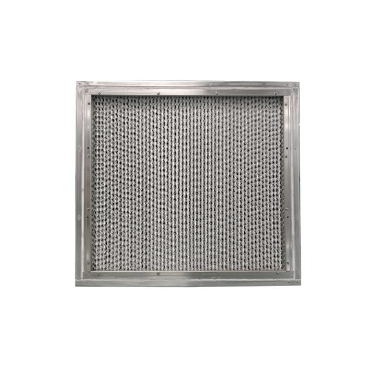
The layer flow transfer window purification + sterilization complete configuration classification It is divided into four major categories: basic layer flow purification system, physical disinfection and sterilization module, high-end all-round sterilization system (VHP), and industry-specific protective purification accessories. Different cleanliness levels, CGT / semiconductor / biosafety laboratories can be selected and equipped as needed. I. Basic layer flow purification system (standard for all layer flow transfer windows) Function: Form vertical unidirectional laminar flow inside the cabin, maintaining a hundred-level cleanliness, isolating cross-zone dust pollution Air supply power unit Common AC centrifugal fan: Economic type, noise is relatively high EC variable frequency energy-saving fan: Standard for pharmaceutical enterprises, semiconductor, GMP sterile workshop, BSL laboratory. Adjustable wind speed, low noise, energy-saving High-efficiency filtration components (core purification) H13 high-efficiency filter: Commonly used in electronic, D-level clean workshops H14 high-efficiency filter: Mandatory standard for GMP sterile workshop, CGT, BSL laboratories Matching accessories: Filter PAO leak detection port, front and rear pressure difference monitor / digital pressure difference, real-time judgment of filter material blockage Air flow structure Top uniform flow membrane + vertical downward laminar flow, bottom return air slot circulation, self-purification time adjustable 5~15 minutes II. Conventional physical sterilization configuration (basic disinfection, low-cost optional)
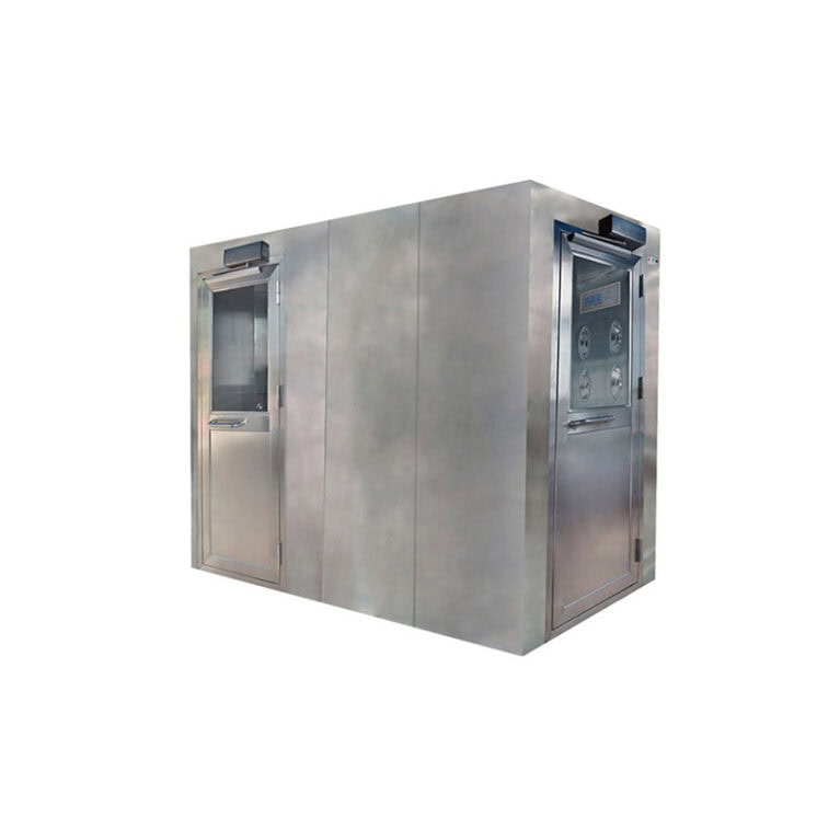
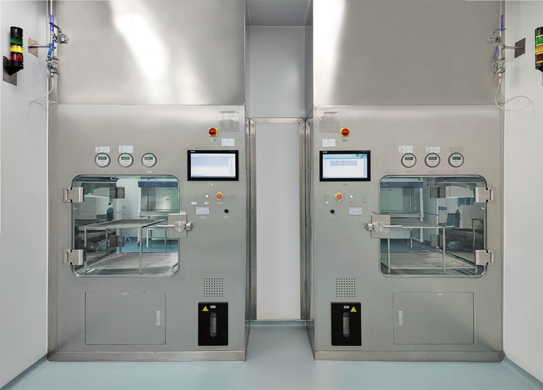
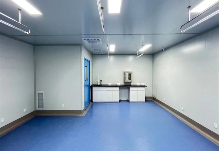
I. Core Advantages of the Automatic Sliding Door Washroom (Automatic Door Washroom) Better air tightness, more stable cleanliness level Steel / stainless steel hard door panels + overall rubber seal around the edges. After closing, the gap is small and the air leakage is low. Suitable for high cleanliness requirements such as A-class, 10,000-level, and 10,000,000-level workshops. It is easier to maintain the pressure difference in the clean room. Hard door body, resistant to cleanliness and disinfection, easy to clean The door panel is made of metal hard structure, which can withstand frequent wiping with alcohol, hydrogen peroxide, and disinfectants, and is not prone to deformation or dust adsorption; there are no dust accumulation dead corners like soft door curtains, making it more suitable for high-standard clean areas in pharmaceuticals, sterile food, and precision electronics. Regular appearance, good visibility Standard double-layer tempered observation window, allowing direct viewing of the interior of the warehouse; the overall structure is integrated, beautiful and tidy, suitable for factories with high visual standards for the workshop. Low operating noise, stable operation Horizontal sliding opening and closing, with little impact; Faults are obvious and maintenance is simple. Interlock system mature, compliance strong The electronic interlock of
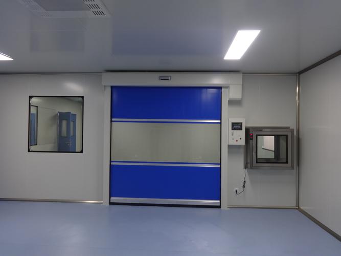
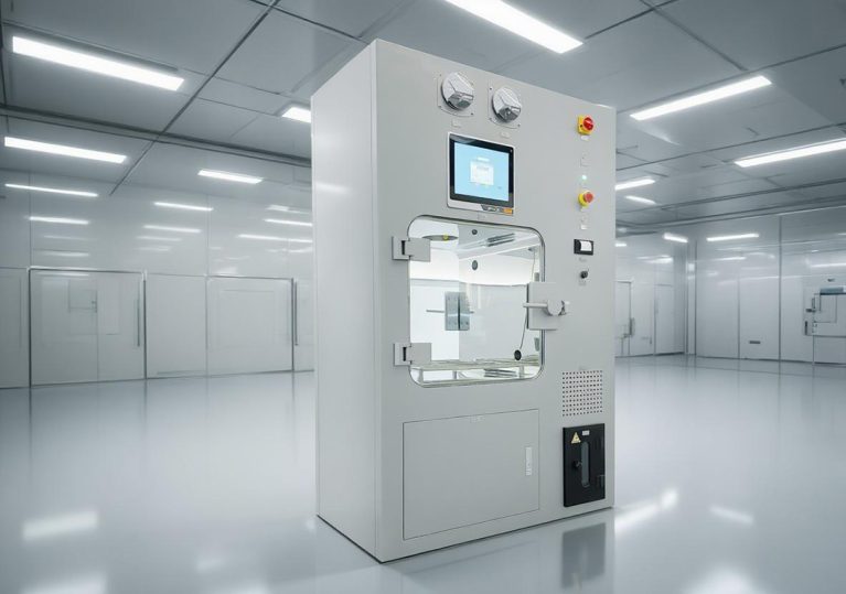
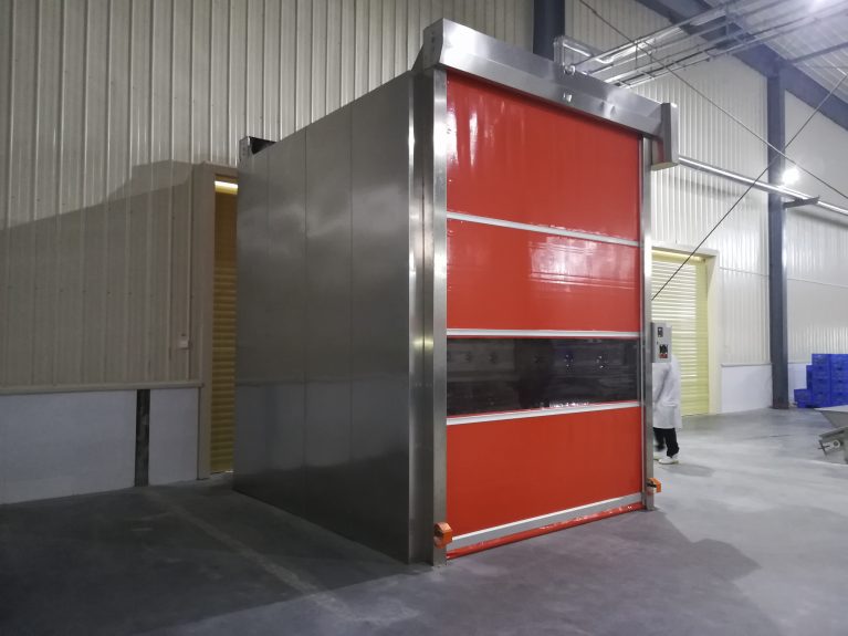
I. Application Scenarios of Automatic Sliding Door Washroom (Hardened Automatic Door Washroom) Core Features: Hardened sealing, excellent airtightness, good cleanliness maintenance, standard door opening dimensions, suitable for trolleys / small AGVs, but not for forklifts. Pharmaceutical Industry Aseptic formulation workshops, raw material drug clean areas, laboratory material passageways, GMP aseptic areas, requiring frequent disinfection and having requirements for sealing. Medical Devices (Aseptic Class II, Class III) Class II and Class III sterile instrument clean workshops, finished product material transfer, requiring no dust accumulation dead corners, tolerance to vaporized hydrogen peroxide and disinfectant wiping. Precision Electronics, Semiconductor, Optical Components Thousand-level, ten-thousand-level clean workshops, PCB, camera module, chip supporting workshops, strict dust control. Food and Beverage (Aseptic Cold Filling, Baking Aseptic Area) Raw materials and semi-finished products transfer channels in the aseptic packaging section. Laboratories, third-party testing clean rooms Transfer of laboratory consumables and samples, high requirements for stable pressure difference. Not Suitable: Forklift entry, oversized pallets, large container goods transfer; locations with no reserved space for sliding doors on both sides. II. Application Scenarios of Quick Rolling Shutter Door Washroom Core Features: Vertical upward movement does not occupy lateral space, can be used as a main door opening, allows for forklift
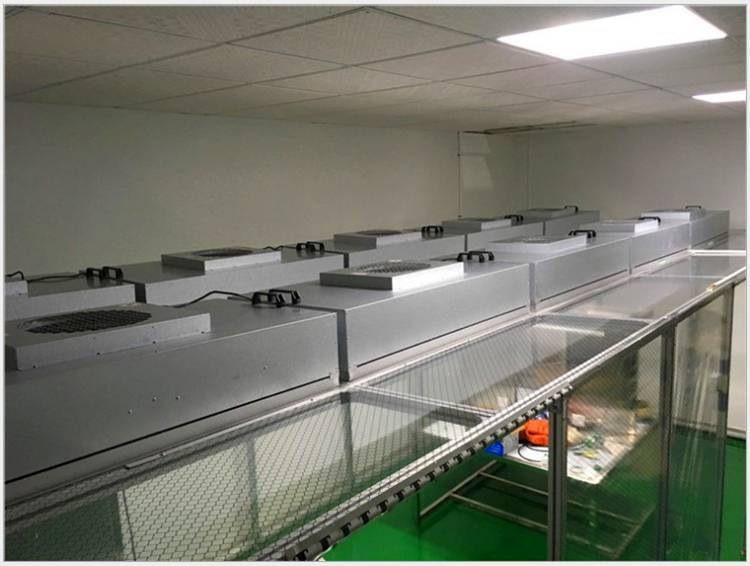
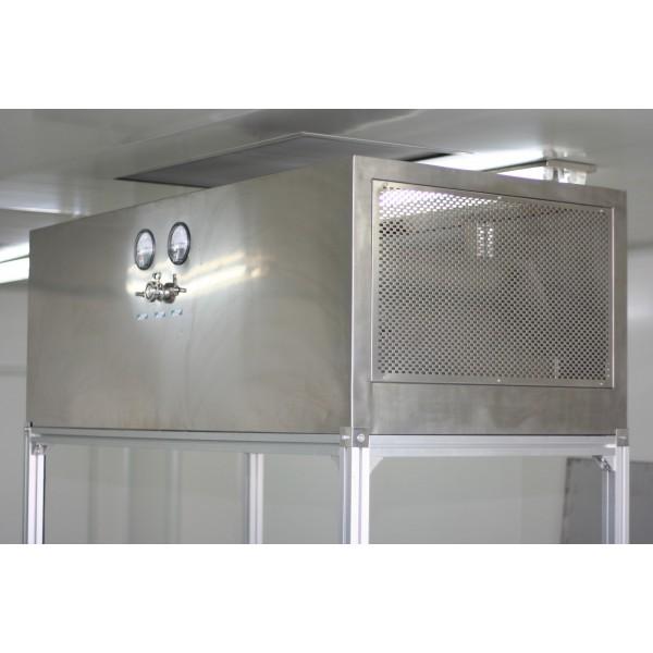
FFU vs A-Class Cleanroom Hood: Complete Lifespan Comparison of the Entire Unit + Accessories I. Design Lifespan of the Entire Unit (Industry standard conditions, pharmaceutical / electronic cleanrooms, daily operation of 8-16 hours) 1. FFU (Fan Filter Unit, galvanized / stainless steel simple housing) 1) EC DC Brushless FFU (High-end GMP model) Fan design lifespan: 8-10,000 hours, conversion: 8 hours/day: 12-15 years 24-hour continuous operation: 9-11 years Overall lifespan of the unit: 8-10 years. After motor aging, the fan can be replaced separately, and the housing can be reused. 2) AC AC FFU (General economy model) Fan lifespan: 3-5,000 hours. The entire unit only lasts 5-7 years. Later, noise and air volume decline significantly. Housing lifespan: Galvanized plate: 10 years or so, prone to rust; 304 stainless steel FFU housing can last over 15 years. 2. A-Class Cleanroom Hood (Fully 304 stainless steel GMP liquid tank sealed model) Design lifespan of the entire unit: 10-15 years. With proper maintenance, it can last up to 15-20 years. Advantages: Thickened stainless steel sealed box, noise reduction static pressure chamber, reinforced frame, corrosion and deformation are much less than ceiling FFU; Internal fans and electrical control can be replaced separately, and the box
A-level laminar flow cabinets & FFU application scenarios are clearly distinguished I. FFU (Fan Filter Unit) application scenarios FFU is a standardized air supply module. Its core function is to provide air supply for large areas of clean spaces. It must be used in conjunction with ceiling brackets and return air systems. 1. Electronics and semiconductor industry Chip packaging, lithography workshops, SMT assembly clean rooms, achieve overall clean environments of 10,000, 10,000, and 10,000 grade respectively. The entire ceiling is covered with FFU to create a clean environment. Assembly clean sheds, mobile clean rooms with top air supply units Battery and photovoltaic component production workshops, large-scale unified purification 2. Pharmaceutical industry (entire A-level area) Aseptic drug filling halls, freeze-drying and packaging workshops, form an A-level environment under the background of B-level clean rooms Full coverage of large-volume injection and aseptic powder injection production lines Air conditioning and ventilation systems for isolation units 3. Laboratories, precision processing Optical lenses, precision instrument assembly workshops Third-party testing clean laboratories, clean partitions for PCR areas with air supply systems 4. Built-in use as a supplement Air supply core components for ultra-clean workstations, clean transfer windows Negative pressure weighing rooms, built-in fan filter units in