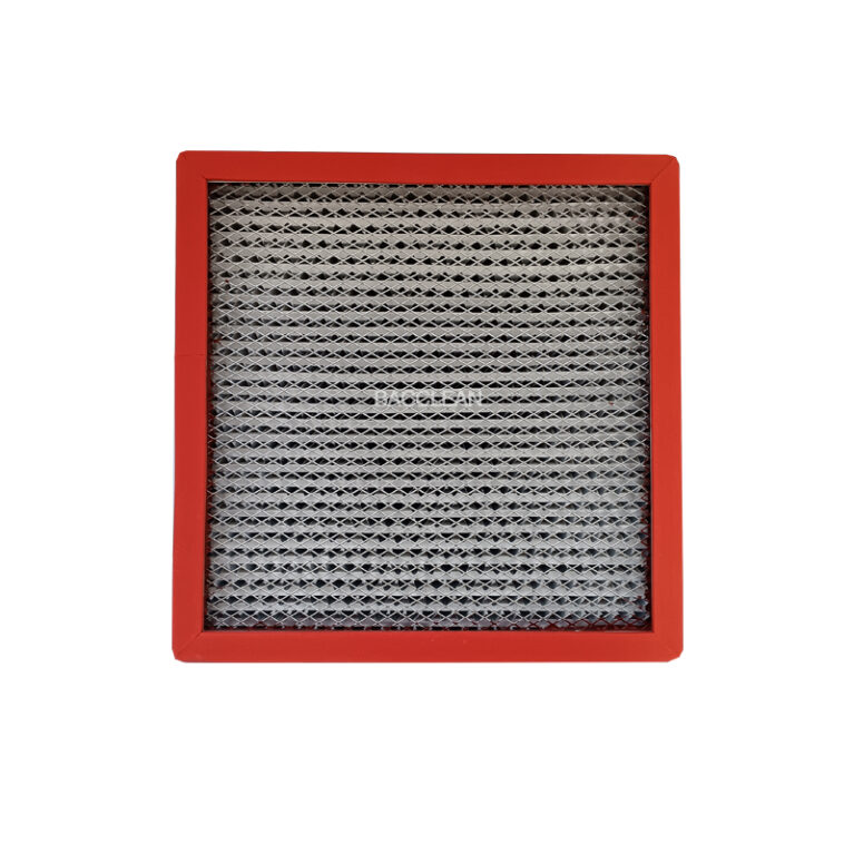
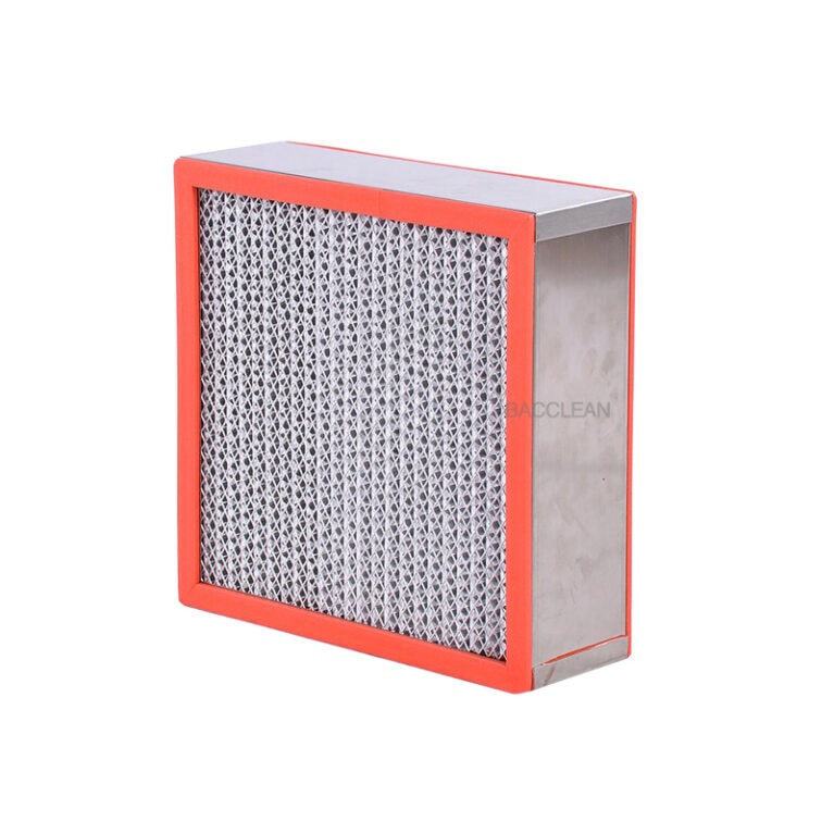
Service life of high-efficiency filters (HEPA) Normal use: 1 to 2 years Harsh environment / High dust: 6 to 12 months Critical clean areas (sterile, high requirements): recommended not to exceed 1 year 1. The actual lifespan is determined not by time, but by these 4 indicators Satisfy any one of them, it must be replaced; it cannot be used any longer: Final resistance reaches twice the initial resistance (The most critical indicator, mandatory for GMP) DOP/PAO leak test fails (leakage rate > 0.01%) Filter paper is damaged, blackened, damp, moldy, or yellowed Use time exceeds 2 years (regardless of pressure difference, it is recommended to force replacement) 2. Tips for extending lifespan (very practical on-site) Primary and secondary filters should be replaced on time (generally 1–3 months) Avoid high humidity, water leakage, and direct spray from water jets towards the air outlet Daily cleaning only wipe the diffusers, do not wipe the high-efficiency filter paper Regularly record the pressure difference and observe the upward trend 3. Summary (can be memorized directly) The theoretical lifespan of high-efficiency filters is 1 to 2 years, In practice, it is replaced when the pressure difference ≥ 2 times the initial resistance, DOP leak
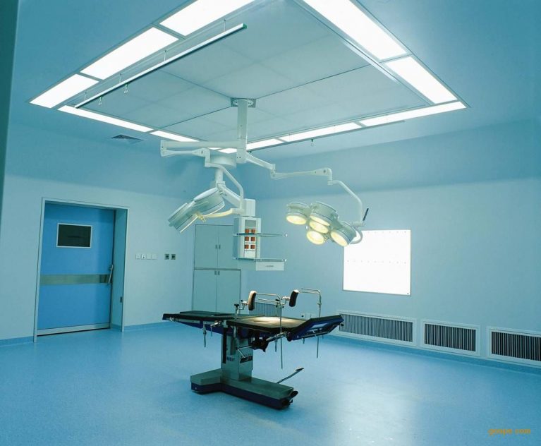
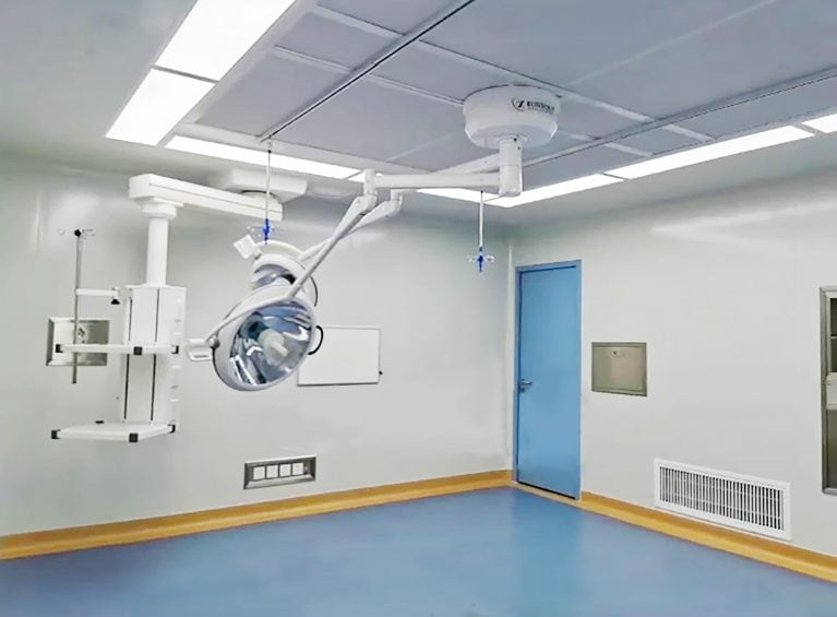
DOP HEPA box Daily Maintenance I. Daily Maintenance Objectives To ensure the integrity of the high-efficiency filter, no air leakage, normal airflow, and meeting the cleanliness standards, in accordance with GMP/ISO requirements. II. Daily Maintenance Contents (Divided into three levels: per shift / per week / per month) 1. Daily Maintenance (Operation Inspection) Visual inspection The supply air panel and diffuser plates are free of dust, stains and deformation. There is no condensation water or mold spots. Operating status The air supply is normal, without whistling or abnormal vibration. The airflow is uniform, without obvious vortex or wind short-circuiting. Pressure difference check (when a pressure difference meter is available) The pressure difference before and after the filter is within the normal range. There is no sudden increase or decrease. Cleaning Use a lint-free cloth and 75% ethanol to gently wipe the surface of the panel and diffuser plate. Do not rinse with water directly, and do not impact the high-efficiency filter. 2. Weekly maintenance (deep cleaning + inspection) Remove the diffuser plate / diffuser panel (operate gently) Clean the diffuser panel and the inner wall of the air outlet Check: Seal strips have no aging, no detachment, no fracture Compression
I. Scope of Application Cleanroom / Transfer Window / Air Shower / Clean Workbench HEPA/ULPA High-Efficiency Filters Method: Aerosol Scanning Leak Detection Method (Upstream Dust Generation + Downstream Scanning) II. Preparations Before Testing 1. Instruments and Consumables Aerosol Photometer (with dual channels for upstream/downstream) Aerosol Generator (heated / cooled PAO/DOP) Isokinetic Sampling Gun, Hose Calibration Certificate within Validity Period Clean Rags, 75% Ethanol 2. System Status Air Conditioner / Fan Running for ≥ 10 minutes continuously Cleanliness Filters Surface Cleaned Free of Dust Clean Area Free of Dust, No Operations, Minimum Personnel All Doors, Windows, Inspection Holes Closed 3. Instrument Preparation Photometer Turned On and Preheated for ≥ 15 minutes Zero Point Calibration, Range Calibration Connect Upstream Sampling Tube to Filter Upstream Static Pressure Box III. Formal Leak Detection Operating Steps (Full Version) Step 1: Establish Upstream Challenge Concentration Connect the aerosol generator to the upstream air duct of the high-efficiency filter Turn on the generator, let the dust generation stabilize for 3-5 minutes Read the upstream concentration with the photometer: Controlled within 10-30 μg/L Photometer Settings: Display Mode: Leakage Rate (% Penetration Rate) Alarm Threshold: ≤ 0.01% Step 2: Zeroing of the Photometer (Baseline Calibration) Confirm the stability of
DOP/PAO High-Efficiency Filter Leak Detection Principle (Full Version) I. Core Sentence Inject aerosol towards the upstream, measure the leakage concentration at the downstream, and determine the integrity of the filter and seal by the “penetration rate”. II. Detailed Principle (GMP/ISO Standard Explanation) 1. What is DOP/PAO DOP: Di-Isopropyl Phthalate, an early used aerosol PAO: Poly α-Ether, the current mainstream, safe, and recommended Both are oily aerosols, capable of generating challenge particles of about 0.3μm — This is precisely the particle size that is most difficult for HEPA filters to filter and most prone to leakage. 2. Leak Detection Physical Principle: Challenge upstream + Scan downstream 1) In the upstream, create a stable concentration of aerosol to heat or cool it and send it into the filter intake side (upstream). Form a uniform and stable challenge concentration C₀. 2) The normal filtration principle of HEPA: HEPA filters have a filtration efficiency of ≥ 99.97% for 0.3μm particles. Under normal circumstances: Upstream: There is aerosol Downstream: Almost undetectable 3) Leakage = Aerosol “circles around” the filter. If any of the following occurs: Filter paper damage Pinholes Border seal not tight Installation gap Rubber strip aging The aerosol will directly leak to the
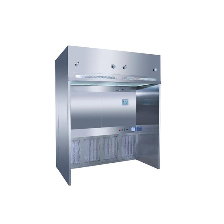
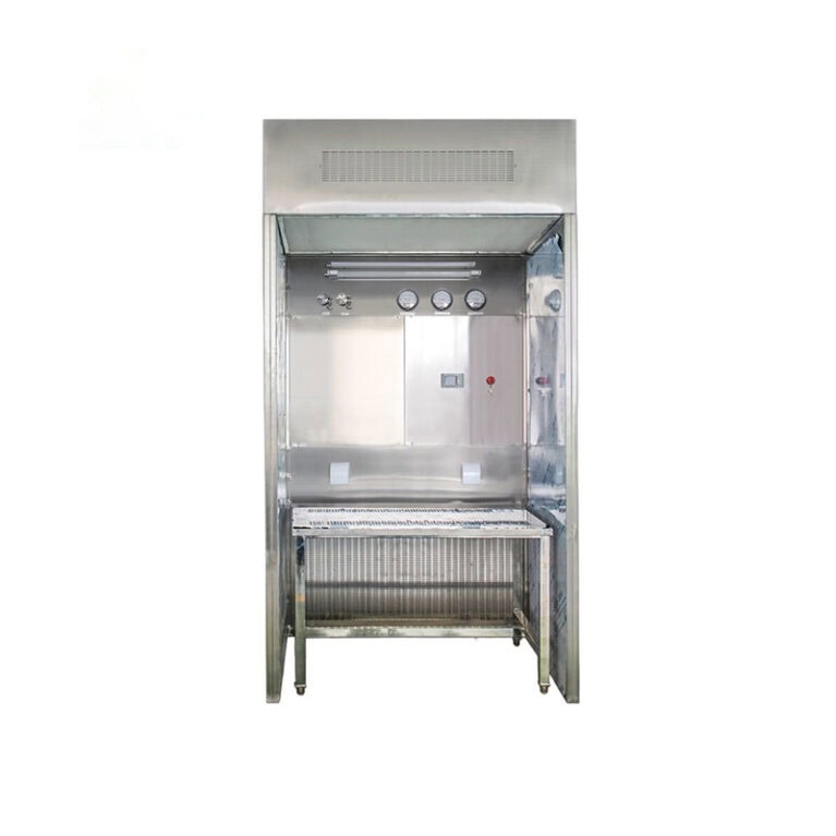
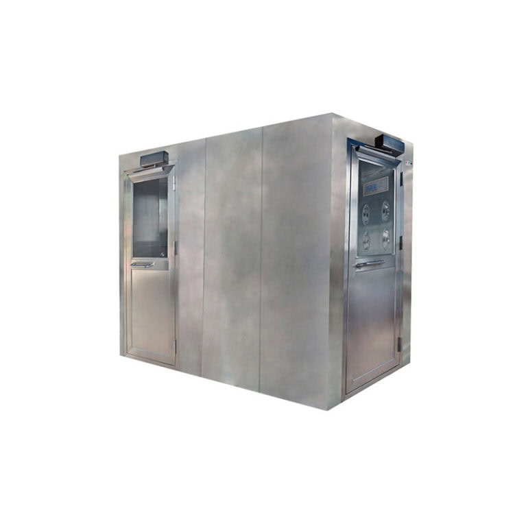
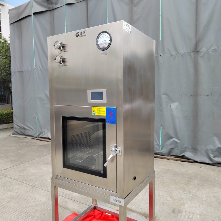
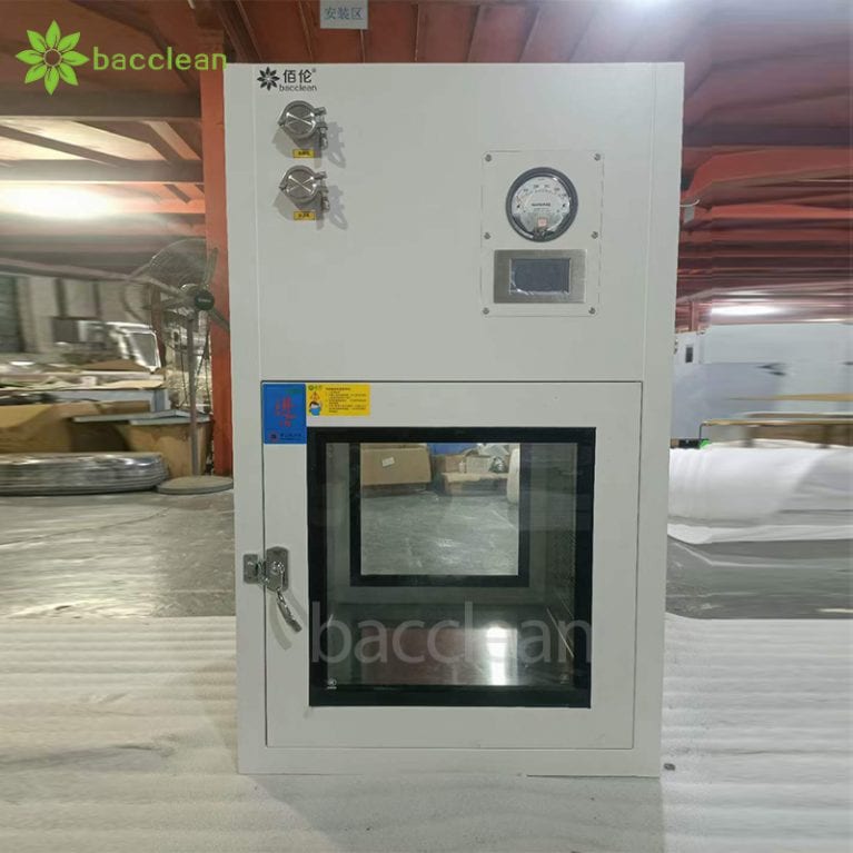
Daily inspection of the DOP (PAO) laminar transfer window focuses on the integrity scanning and leak detection of the high-efficiency filters to ensure no leakage and that the filtration efficiency meets the standards. This is a key daily inspection for controlling contamination in the clean area. I. Inspection Objectives Verify that the HEPA/ULPA filters are undamaged and leak-free Confirm the integrity of the sealing structure (frame, joint, installation surface) Meet the compliance requirements of GMP, ISO 14644, GB 50591, etc. for clean rooms II. Inspection Cycle (Daily / Routine) Daily inspection: per shift / daily (visual + simple functional check) Regular DOP scanning: once every quarter (key areas can be monthly) Annual full performance: including DOP, air velocity, cleanliness, pressure difference, interlock III. Preparations Before Inspection 1. Equipment and Consumables Aerosol generator (heated DOP / cold PAO) Aerosol photometer (with upstream/downstream dual channels, accuracy 0.01%) Wind speed meter, pressure gauge, dust particle counter Clean cloths, alcohol, sealant (for backup) 2. Environment and Status The transfer window is operating normally (fan, UV, interlock, self-cleaning) There is no cross-operation in the clean area, adjacent doors/windows are closed The instrument is preheated for ≥ 15 minutes, calibrated / reset Clean the surface of
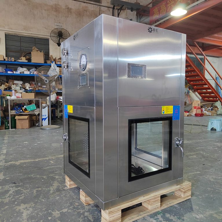
I. First, clarify: Daily inspection = two parts Functional daily check (per shift / daily) DOP/PAO high-efficiency filter leak detection (performed regularly, not measured every day during daily inspection) I will provide you with the most standard, detailed, and writeable SOP process. II. Daily functional check for DOP/PAO laminar transfer window (per shift must be done) 1. Appearance and cleanliness Check the inner and outer surfaces of the transfer window, glass, door frame for no stains, no damage, no rust Seal strip flat, no deformation, no detachment No debris, no water accumulation, no odor inside 2. Interlock function When one side door is opened → the other side must be unable to open After closing, the interlock automatically resets, with normal sound and light indication 3. Fan / laminar operation After starting, the fan operates smoothly, without abnormal noise, without vibration The airflow at the outlet is uniform, without obvious turbulence The operation indicator light is normal 4. Ultraviolet germicidal lamp The lamp lights up normally, without flickering, without blackening The timing is accurate, the cumulative usage time has not exceeded the lifespan (generally 9000 hours) 5. Pressure difference (if any) The pressure on the clean side is higher than
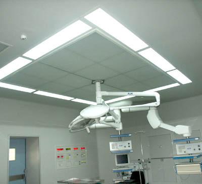
Ensure that the daily maintenance records of the air supply ceiling are accurate. The key points are: accurate instruments, true data collection, strict filling, thorough verification, and clear standards. This will prevent “estimated, fabricated, modified, or incorrect” data from being generated at the source. Here is a set of actionable measures you can follow: 1. First, ensure that the measurement data is accurate. The instruments must be calibrated regularly. Pressure gauges, anemometers, temperature and humidity meters, etc., should be sent for calibration at regular intervals, and the calibration certificates should be attached. Any expired or non-compliant instruments must not be used. Before use, conduct a self-check. Before measuring the pressure difference, check if the zero point is normal; Before measuring the wind speed, confirm that the probe is clean and in the correct position. Use a unified measurement method. Fix the measurement point position, height, and reading time to avoid data deviation due to different individuals. 2. Second, ensure that the record process is true and not falsified. Numbers must be written: pressure difference XX Pa, wind speed XX m/s, resistance XX Pa. Fill in immediately after maintenance, without relying on memory or centralized re-filling. Only write the measured values,
The accuracy of the maintenance records for the air supply ceiling directly determines whether the cleanroom can operate stably, comply with standards, control risks, and reduce costs. Once the data is inaccurate, it will have a chain effect on the overall operation of the cleanroom in five aspects: environment, quality, compliance, equipment, and cost. 1. It directly determines whether the cleanliness of the cleanroom truly meets the standards. Accurate records: They can truly reflect the resistance of the filter, pressure difference, air velocity, and sealing status, and promptly detect efficient blockage, air leakage, and uneven airflow, ensuring that suspended particles and settled bacteria meet the standards. Inaccurate records: False data / incorrect data will cover up filter failure, static pressure box leakage, and diffuser plate contamination, making it seem normal but the cleanliness has exceeded the standard, and the cleanroom becomes meaningless. 2. It determines whether equipment failures can be predicted in advance and avoid sudden production line shutdowns. Accurate records: Through resistance trends, pressure difference fluctuations, and wind speed changes, it can predict the lifespan of the filter and component aging, achieving preventive maintenance. Inaccurate records: It cannot identify abnormal trends, resulting in sudden filter leakage, sudden drop in
Ensure that the maintenance records of the air supply ceiling ( laminar flow ceiling / efficient air supply outlets ) are complete, compliant, and traceable. The key is to achieve full coverage of content, standardized filling, closed-loop process, and secure storage, while also meeting the compliance requirements of clean rooms (GMP/ISO14644). Here are the practical methods that can be directly implemented: 1. First, clarify: All dimensions that must be recorded (no omissions) The maintenance records of the air supply ceiling cannot simply state “normal”; they must cover all aspects including structure, filtration, airflow, components, environment, and personnel: Basic Information Room number / Cleanliness level, supply air ceiling number, installation location, record date / time, operator / reviewer. Daily inspection items (must be noted) Appearance: No damage, dust accumulation, deformation, loosening of the diffuser plate / uniform flow membrane; Sealing of the frame is intact Pressure difference: Inlet/outlet pressure difference of the high-efficiency filter, pressure difference reading, comparison with the reference value Wind speed / airflow: Uniformity of the outlet wind speed, presence of vortex, dead corners Sealing: No air leakage, condensation, abnormal noise in the static pressure box, flange, soft connection Cleaning and disinfection record Cleaning method (wiping / vacuuming),
The retention period for the daily maintenance records of the air supply ceiling is mainly determined in accordance with industry regulations/standards, taking into account both the need for product traceability and the management of the equipment’s entire life cycle. Daily records and key verification/replace records can be set at different levels to ensure compliance and traceability. The following are clear, actionable standards and practical suggestions. 1. Core regulations and general benchmarks The maintenance records of the air supply ceiling, as a core component of the HVAC system in a cleanroom, must first follow the mandatory industry norms. ISO14644 mainly emphasizes traceability and does not mandate a uniform retention period; the core constraints come from various industry-specific regulations: Pharmaceutical GMP (2010 edition): Equipment maintenance records should be kept until one year after the expiration date of the drug; for drugs without an expiration date, at least five years should be kept; verification records (including PAO leak detection) are recommended to be kept until one year after the equipment is scrapped, with a minimum of five years. Medical device GMP: General records should be kept for at least two years from the date of product release or the product’s lifespan (whichever is
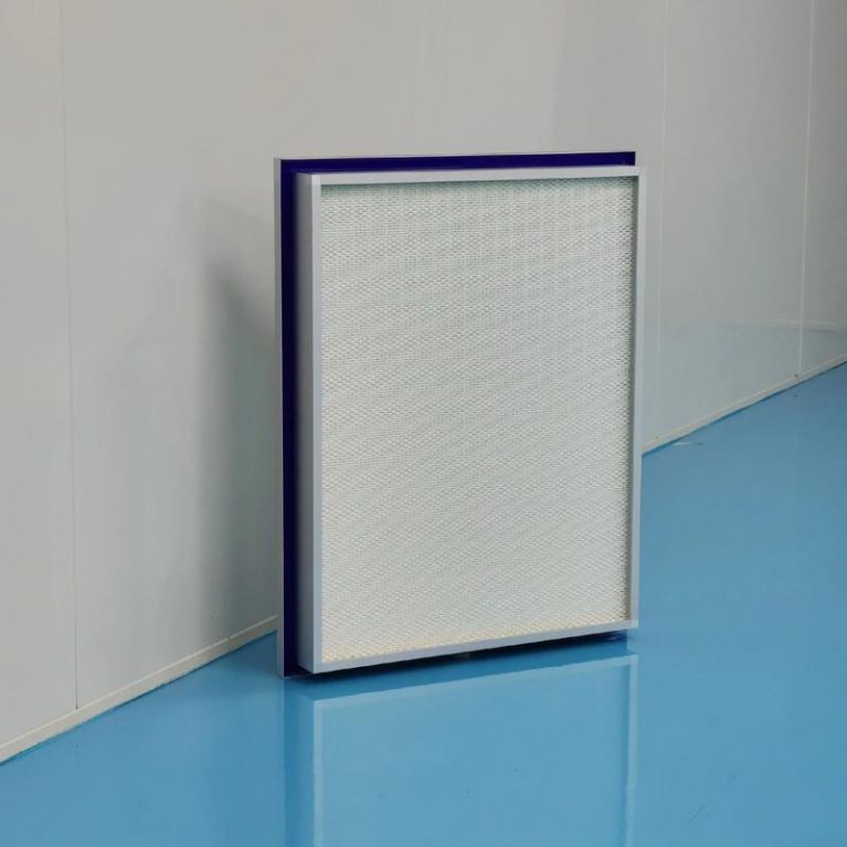
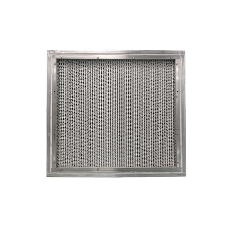
The leak detection determination for DOP high-efficiency liquid filter is based on the core standard of **≤0.01% penetration rate (leakage rate)**. It is accompanied by repair and re-test rules, which need to cover the filter material, seal, and frame, and meet the specifications such as ISO 14644-3 and GB/T 6165-2008. Here are the determination criteria and practical key points: Core determination indicators Penetration rate threshold: The continuous and stable penetration rate of all scanable points of the filter ≤ 0.01% (that is, one ten-thousandth of the upstream concentration), any point exceeding this threshold is judged as不合格, and it needs to be marked for repair or replacement. Scan coverage range: Filter material surface, filter material – frame bonding area, frame – liquid tank sealing surface, liquid tank – static pressure box / enclosure joint, frame joint seam, etc. Detection parameters: Scan speed ≤ 5cm/s, probe distance from the filter surface is approximately 25mm, line overlap ≥ 10mm; the upstream aerosol concentration is stable at 10–20μg/mL (or meets the instrument linear range). Repair and re-test rules Project Qualified upper limit Re-test requirements Single repair length ≤38mm After repair, a re-measurement of the entire area was conducted, and the penetration rate remained ≤
The leak detection of the DOP (now mostly using PAO) high-efficiency liquid tank filter is based on the principle of upstream dust generation and downstream scanning. It involves detecting the transmittance using a photometer to determine whether the filter material, the liquid tank seal, and the frame are leaking, strictly following ISO 14644-3, GB/T 6165-2008, and GMP standards. The operation process is divided into 6 core stages, covering the entire process and being feasible for implementation: 1. Preparations before leak detection (key points: calibration + system confirmation) Instrument calibration and inspection Aerosol photometer: Start the machine for 30 minutes of preheating, complete zero calibration and 100% concentration calibration (using upstream standard aerosol), confirm the range and response time are normal, and the probe is not clogged. Dusting device: Check the oil level of DOP/PAO, heating temperature, and nozzle status to ensure stable dusting; Connect the air compressor to confirm the pressure and flow meet the standards. Auxiliary tools: Prepare scanning probes, extension rods, marker pens, record sheets, sealant / patches (for compliant repair), and differential pressure gauges. System and filter status confirmation Air conditioning system: Turn on the fan corresponding to the target high-efficiency filter, run stably for ≥ 30