
1 Core Regulatory Requirements
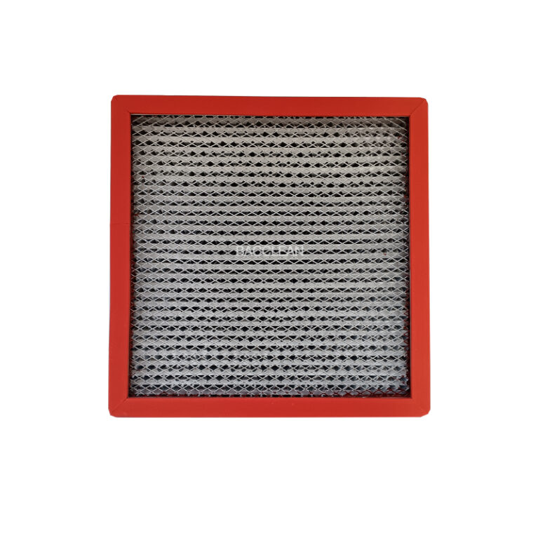
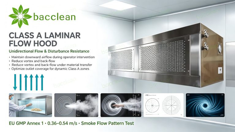
EU GMP Annex 1 specifies the unidirectional‑flow air velocity for Class A zones as 0.36‑0.54 m/s. It emphasizes that under dynamic conditions, no significant vortex or back‑flow shall occur after human‑operator and material interventions. Smoke flow pattern test serves as an important visual verification method. Full‑coverage PAO leak test shall be performed for filters. Equipment structures shall be free of dead corners and compatible with cleaning and VHP sterilization.
GB/T 45128‑2026 also defines explicit indicators for unidirectional‑flow equipment regarding air‑velocity uniformity, disturbance resistance and air‑tightness. Numerous projects only conduct no‑load air‑velocity measurement while ignoring dynamic‑disturbance scenarios, resulting in major non‑conformities during acceptance.
2 Key Design Points for Plenum Chamber

The plenum chamber forms the foundation of unidirectional airflow. It converts fan dynamic pressure into static pressure to achieve uniform air supply across the entire filter outlet face. ① Sufficient internal volume: undersized plenums tend to generate deflected airflow, giving rise to locally excessive or insufficient air velocity. ② Optimized internal flow‑guide structures to prevent direct airflow impingement on partial filter areas. ③ Adequate cabinet rigidity to avoid vibration during operation and secondary dust re‑entrainment. ④ Superior air‑tightness: plenum air leakage will lead to insufficient air volume for partial filter sections.
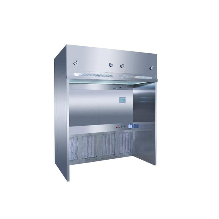
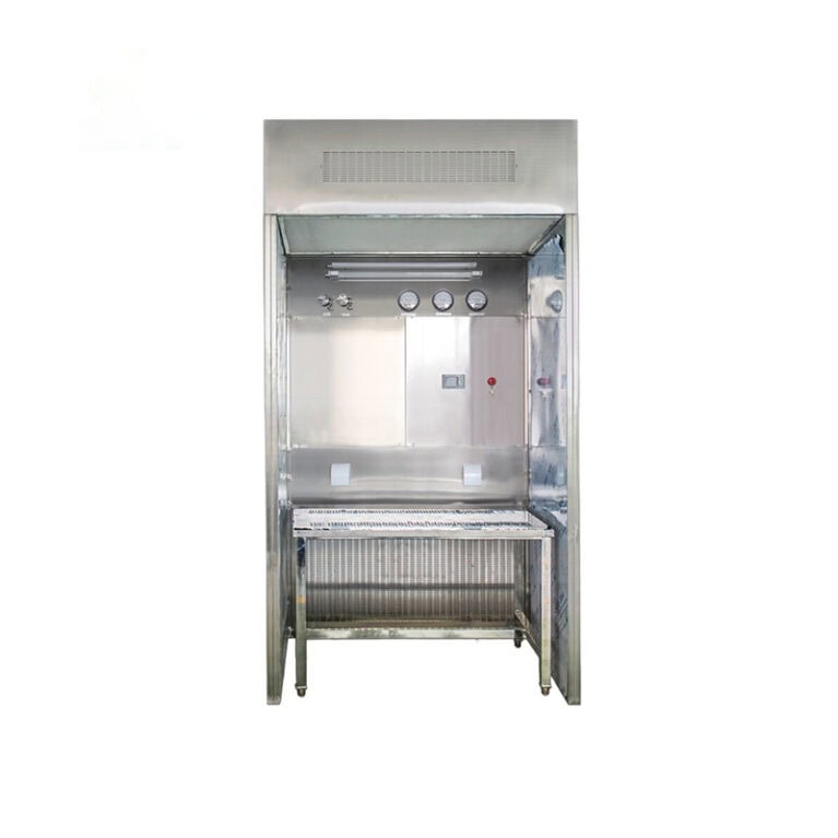
bacclean Class A laminar flow hoods adopt large‑volume optimized plenum chambers equipped with internal flow baffles to mitigate airflow deflection and guarantee uniform air discharge over the full filter face.
3 Flow‑Uniformizing System Technology
Satisfactory uniform unidirectional flow cannot be achieved by filters alone; flow‑uniformizing membranes / meshes are critically important. Inferior flow‑uniformizing components may induce local vortexes. The flow‑uniformizing system shall deliver low air‑velocity dispersion across the discharge face, suppress turbulence and establish stable downward unidirectional flow. CFD simulations evaluate performance of different flow‑uniformizing components to optimize opening ratio and layout, attenuate fan‑generated turbulence and secure unidirectional airflow within the operating zone.
4 Fan Selection and Static‑Pressure Margin
Fans for Class A laminar flow hoods shall overcome resistance from pre‑filters and HEPA filters as well as pressure losses inside the plenum chamber. Filter resistance rises over service time, so fans must carry sufficient static‑pressure margin. Insufficient margin will trigger rapid air‑velocity drop and failure of unidirectional flow once filters become clogged. EC variable‑frequency fans are preferred, featuring adjustable air velocity, real‑time operating‑parameter monitoring and convenient maintenance.
5 Disturbance‑Resistant Design
Dynamic disturbances originate from operator arm insertion, material transfer and tooling equipment. Objects intruding into Class A zones block airflow and readily produce local vortex and back‑flow. During design phase, CFD simulations replicate scenarios of arm and material intervention. The discharge‑face dimension is optimized to secure adequate unidirectional‑flow coverage for the operating area. Even with object intrusion, surrounding airflow maintains downward direction and reduces entrainment of surrounding Class B air. Many low‑cost laminar flow hoods feature an outlet area barely covering the work surface. Once an operator’s arm reaches into the working zone, side‑stream back‑flow emerges and causes failure of dynamic flow‑pattern qualification.
6 On‑Site Validation Checkpoints
- Multi‑point air‑velocity test: Collect readings across operating zones; measured values shall fall within 0.36‑0.54 m/s with dispersion complying with specifications.
- Smoke flow‑pattern test: Visual inspection confirms continuous downward airflow without obvious vortex or upward back‑flow. Observe airflow recovery after simulated manual operations.
- PAO leak test: Complete filter leak detection with zero leakage.
- Dynamic particle counting: Particle concentration shall meet Class A requirements under simulated operating conditions.
- Structural inspection: Verify dead‑corner‑free construction and intact sealing performance.
7 Selection Pitfall Avoidance
Filter grade alone shall not dominate procurement evaluation. Key evaluation items include: plenum‑chamber volume, fan static‑pressure margin, flow‑uniformizing‑system design, availability of CFD simulation under disturbance scenarios, and supplied smoke flow‑pattern test reports. Pure cost‑oriented purchasing frequently results in equipment passing static tests yet failing dynamically.
8 Summary

The core performance metric for Class A laminar‑flow‑hood unidirectional airflow lies not in static no‑load status, but in dynamic disturbance‑resistance capability. Plenum‑chamber design, flow‑uniformizing configuration, fan pressure margin and disturbance‑condition CFD simulation constitute the four technical pillars. All Class A laminar flow hoods supplied by bacclean undergo CFD simulation under disturbance conditions and complete factory performance testing, accompanied by full validation documentation, assisting customers in satisfying dynamic Class A requirements of EU GMP Annex 1.
