
1. Definition of Basic Parameters & Preconditions for Selection
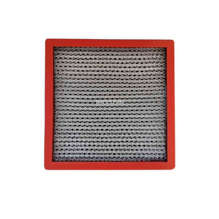
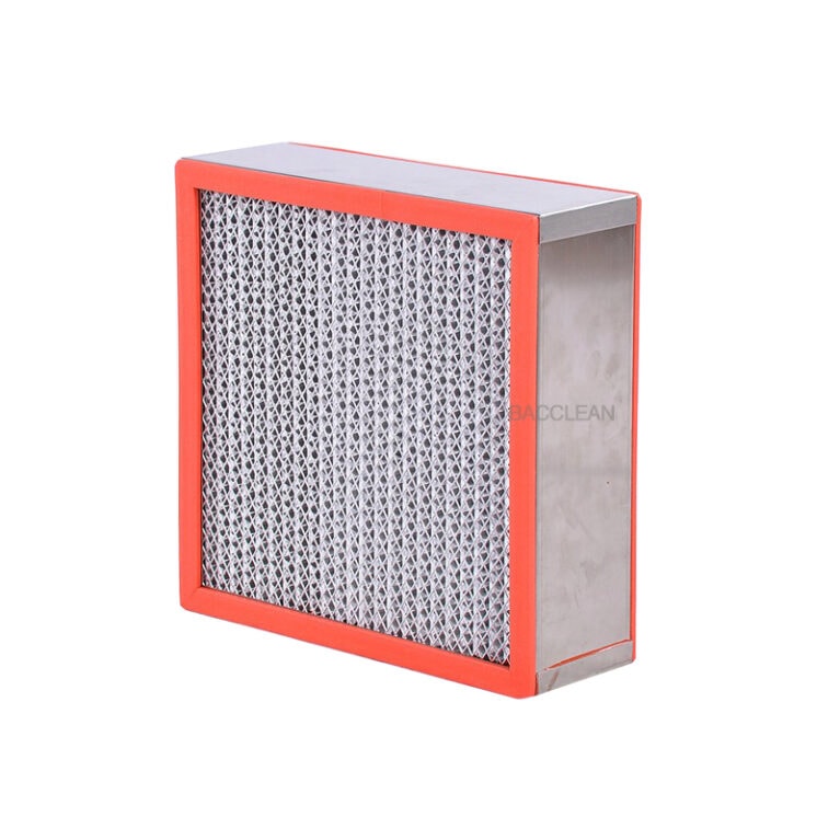
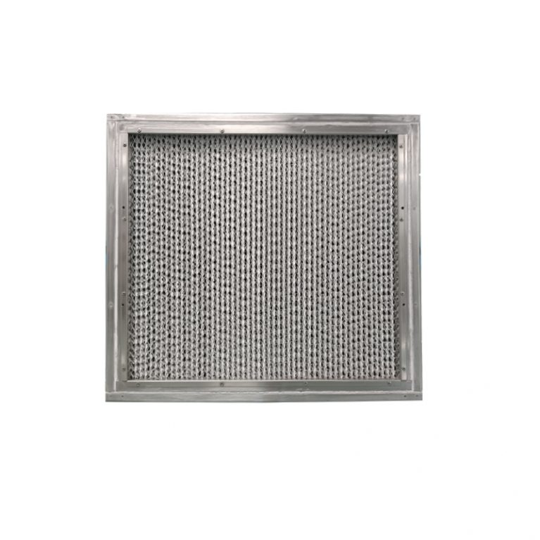
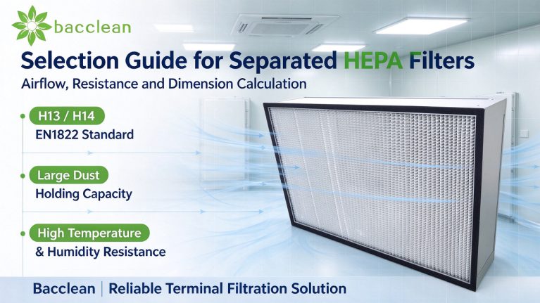
Separated HEPA filters generally adopt aluminum foil separators to separate glass fiber filter media, with paper separators and plastic separators as alternatives. Three frame materials are available: aluminum alloy, galvanized steel and stainless steel. The first step of selection is to clarify the application scenario: positive pressure air supply or negative pressure exhaust, and whether there are fluctuations in temperature and humidity, water vapor, chemical corrosion or AMC molecular pollution risks. Airflow is the primary basis for filter selection, divided into rated airflow and actual operating airflow. Rated airflow is calibrated by the manufacturer under standard working conditions and standard filter media velocity, serving as the benchmark parameter. Long-term operation exceeding rated airflow is not recommended. The actual operating airflow is determined by process requirements, and airflow margin must be reserved in cleanroom design. Resistance includes initial resistance and final resistance. Initial resistance refers to the pressure loss of a new filter under rated airflow, which is the basis for the selection of air ducts and fans. Final resistance is the resistance when the filter reaches designed dust saturation and is recommended for replacement. It is usually provided by the manufacturer combined with filter media and separator structure, and also serves as a reference for differential pressure alarm setting. Filter media velocity is a hidden core indicator, referring to the velocity of airflow passing through the filter paper surface, different from the face velocity of the filter cross-section. The recommended filter media velocity for conventional separated HEPA filters ranges from 0.03 to 0.06 m/s. Lower velocity brings better stability of filtration efficiency, slower resistance rise and longer dust holding life. Higher velocity results in low initial resistance, but the resistance rises rapidly after dust accumulation, shortening service life and adversely affecting particle capture stability.
2. Matching Calculation Logic of Airflow and Dimension
The effective air outlet cross-sectional area of the filter is obtained by subtracting the area occupied by the frame and sealing structure from the nominal dimension. The commonly marked dimension is width × height × depth, with typical depths of 90mm, 150mm and 220mm. Greater depth allows more pleats of filter media, larger total filter media area, lower filter media velocity and lower resistance under the same airflow. The rated airflow of a single filter is directly related to the total filter media area: Total filter media area = length of single pleat × effective height of filter media × number of pleats The number of pleats is determined by separator height, filter depth and separator spacing. Smaller separator spacing allows more filter media to be arranged within the same depth and a larger filter media area. Simplified engineering calculation logic: First confirm the total airflow required by the system, then allocate the airflow for a single filter, check whether the filter media velocity under this airflow falls within a reasonable range, and then reverse the filter specification. General engineering example: A laminar flow hood requires an airflow of 1000 m³/h, with H13 separated HEPA selected and the filter media velocity preferably controlled at about 0.04 m/s. Unit conversion: Q (m³/s)=1000÷3600≈0.278 m³/s; Filter media area A=Q/v=0.278÷0.04≈6.95 ㎡. Select a filter specification with total filter media area larger than the calculated value instead of only checking the outer cross-sectional dimension. Many purchasers mistakenly calculate the filter media velocity directly with the filter face cross-section, which is the face velocity rather than the filter media velocity and will lead to serious misjudgment. The face velocity generally ranges from 0.45 to 0.7 m/s, which is only for reference and cannot be used to judge filtration performance. For filters with the same outer dimension, the thick version (220mm vs 150mm) has a larger filter media area, lower filter media velocity under the same operating airflow, lower initial resistance and longer service life. If only a thin version can be selected due to space limitation, the airflow burden of a single unit shall be reduced and multiple units shall be connected in parallel to share the load. When multiple filters are connected in parallel, filters of the same model and batch shall be selected as far as possible to ensure balanced resistance, avoid biased flow and prevent overload and premature clogging of partial filters. The total airflow of parallel connection equals the sum of airflow of each unit, and the total resistance is basically consistent with that of a single unit.
3. Resistance Calculation, Fan Selection and Differential Pressure Alarm Setting
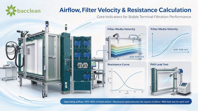
The resistance curve of separated HEPA filters is non-linear, and the resistance continues to rise as dust accumulates. The initial resistance is determined by filter media velocity, filter media type and separator flow channel structure. Under rated airflow, the conventional initial resistance of H13 glass fiber separated HEPA filters is about 220~280Pa, and H14 grade has slightly higher initial resistance. If the operating airflow is reduced, the actual initial resistance will decrease obviously. The resistance is approximately proportional to the square of airflow, which is a general rule for air duct system resistance. Simplified resistance conversion formula: Q1/Q2=√(ΔP1/ΔP2). The resistance change can be approximately estimated after airflow change for the same filter. For example, the rated airflow is 1000m³/h and the initial resistance is 250Pa; if the actual airflow is only 700m³/h, the actual initial resistance≈250×(700/1000)²≈122.5Pa. This estimation is suitable for glass fiber HEPA filters and is only for preliminary scheme reference. The final value shall be subject to the measured curve provided by the manufacturer. For final resistance setting, twice the initial resistance is recommended for conventional working conditions. For a filter with an initial resistance of 250Pa, the final resistance alarm can be set at 450~500Pa. For high-dust and high-dust-generation scenarios such as weighing booth exhaust and process exhaust, the final resistance shall be appropriately reduced to prevent severe airflow attenuation caused by excessive resistance and damage to clean airflow. For fan selection of the system, the initial resistance of HEPA filters, air duct resistance, plenum resistance and pre-filter resistance must be superimposed, and a resistance margin of 15%~25% shall be reserved to avoid insufficient airflow in the middle and later period of filter dust accumulation and failure to meet the standards of laminar velocity and room differential pressure. Differential pressure monitoring points shall be arranged at the upstream and downstream static pressure interfaces of the filter to collect the resistance of the filter itself, instead of mixing with the resistance of the whole box and air duct, so as to ensure that the reading of the differential pressure gauge truly reflects the clogging state of the filter.
4. Matching of Efficiency Grade, Separator Material and Frame Selection
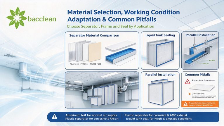
The separator material directly affects the applicable working conditions and is easily ignored in selection. Aluminum foil separators have good rigidity and stable flow channels, which are the first choice for most normal-temperature air supply cleanrooms. Paper separators have lower cost but are not resistant to moisture and water vapor, and are forbidden for high-humidity, frequently cleaned and exhaust conditions. Plastic separators have better corrosion resistance than aluminum foil and are suitable for special exhaust containing weak acid and weak alkali vapor and AMC control. For efficiency grade selection, H13 can meet ISO5 and ISO6 grades for terminal air supply of ordinary cleanrooms. H14 is preferred for GMP sterile areas, weighing booth exhaust and high-risk isolation exhaust, and PAO leak test for each unit before delivery is required. It should be noted that the leak test of separated HEPA filters scans the filter surface, separator gaps, sealing gaskets and frame joints. The bonding position between separators and filter media is a high-leakage point, and low-cost products are prone to micro-leakage here. Sealing schemes are divided into liquid tank sealing and compression sealing. Liquid tank sealing is suitable for high-grade cleanrooms and core air supply terminals that cannot be shut down for replacement. Ordinary compression sealing with gaskets has lower cost and is suitable for positions such as laminar flow hoods, FFUs and self-cleaning pass boxes that are easy to shut down for replacement. Gasket materials include ordinary silicone, EPDM and silicone-free rubber. Silicone-free sealing must be specified for electronic AMC control projects. In terms of temperature resistance, conventional glass fiber + aluminum foil separator can be continuously used at ≤80℃, while special high-temperature models can reach above 250℃ for high-temperature drying exhaust. Ordinary sealant and gaskets cannot be selected for high-temperature working conditions.
5. Margin, Working Condition Correction and Common Selection Mistakes
Airflow margin design: For clean terminal filters, the actual operating airflow is recommended to be controlled at 70%~85% of the rated airflow. Long-term operation at full or over-rated airflow is not allowed. Over-airflow operation will bring three problems: increased filter media velocity and higher risk of efficiency attenuation; sharp rise of initial resistance and increased fan load; significantly shortened dust holding life and more frequent replacement. Working condition correction: Air density changes with temperature and humidity. Airflow and resistance need density correction for high-temperature and high-altitude projects. Separated HEPA filters are not suitable for direct use under working conditions containing oil mist and viscous dust. A pre-filter or activated carbon adsorption section must be configured at the front end. Viscous dust will block the filter media channels, leading to rapid resistance rise and failure to reach the designed service life. Frequent selection misunderstandings:
-
Only compare outer dimensions without checking filter media area and rated airflow. The rated airflow varies greatly among manufacturers with different pleat numbers even for the same outer frame size.
-
Judge performance directly by face velocity and confuse face velocity with filter media velocity.
-
No resistance margin reserved for fans, resulting in airflow drop after filter use and failure to meet the standards of cleanliness and laminar velocity.
-
Paper separator filters are selected for humid and exhaust scenarios, which will absorb moisture, swell and leak air in a short time and become scrapped.
-
Simple frames only suitable for positive pressure air supply are selected for negative pressure exhaust conditions, resulting in frame deformation and sealing failure under negative pressure.
6. Summary of Selection Steps
Step 1: Confirm the total airflow of process requirements and working conditions: temperature, humidity, negative pressure exhaust or not, chemical gas and AMC control or not. Step 2: Determine filtration efficiency H13/H14, separator and frame material, and sealing form. Step 3: Allocate the airflow borne by a single filter, control the operating airflow at 70%~85% of the rated airflow, calculate the filter media velocity and keep it within 0.03~0.06m/s. Step 4: Obtain the initial resistance curve from the manufacturer’s datasheet, calculate the total system resistance and select the fan. Step 5: Set the final resistance alarm value and determine the differential pressure monitoring scheme. Step 6: Check the installation space and confirm the filter depth, installation method (liquid tank / compression) and sealing material. Step 7: Agree on factory inspection requirements: PAO leak test by scanning for each unit, airflow and resistance test report.
Conclusion
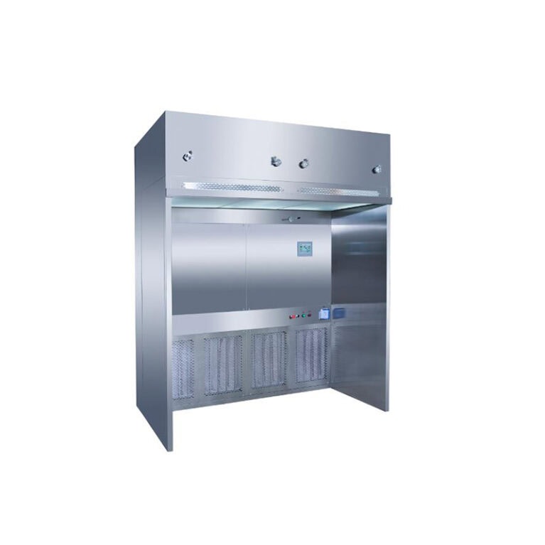
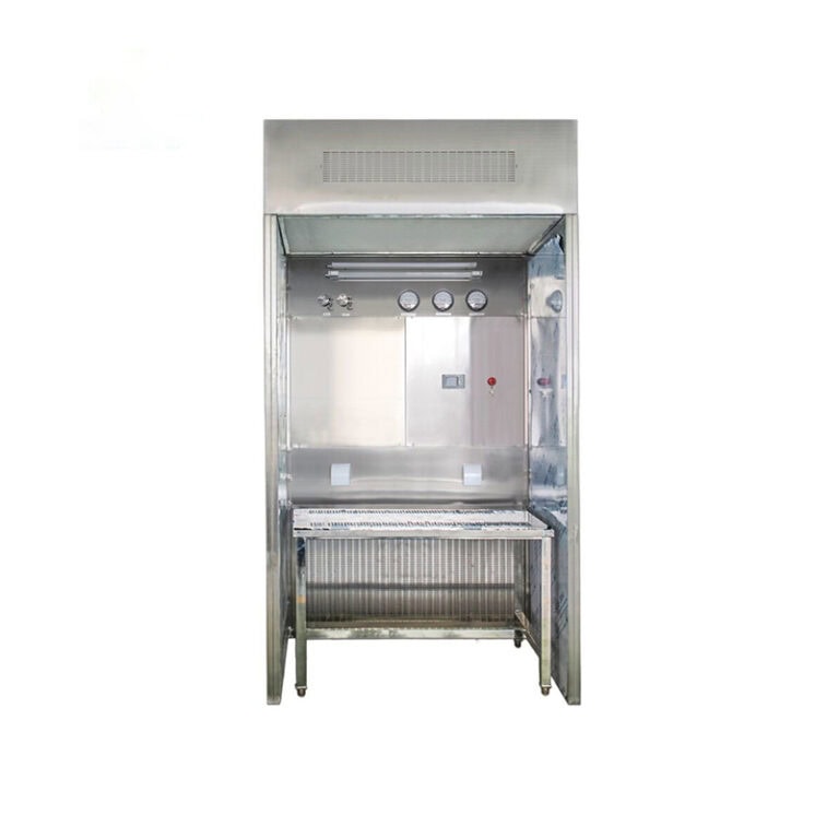
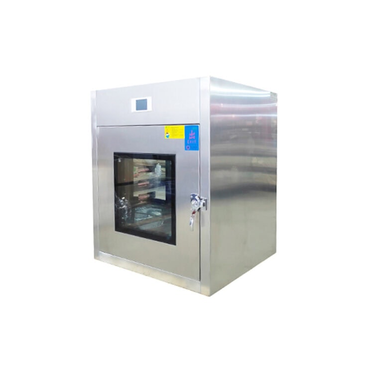
The selection of separated HEPA filters cannot only depend on dimension and price. The core is centered on three main lines: airflow allocation, filter media velocity control and resistance matching. Filter media velocity determines filtration stability and service life, initial resistance determines fan configuration, and final resistance determines replacement cycle and alarm strategy. For high-airflow, high dust holding capacity and moisture-resistant exhaust scenarios, separated HEPA filters have prominent advantages over mini-pleat HEPA filters. However, the separator and sealing material shall be selected according to temperature, humidity, pressure direction and chemical environment, and a reasonable airflow margin shall be matched to maintain the designed performance of the clean system stably for a long time. Bacclean can provide H13/H14 grade separated HEPA filters with aluminum foil separators and stainless steel frames and liquid tank sealing type, supporting PAO leak test, airflow and resistance test services, adapted to terminal purification systems such as cleanroom air supply, laminar flow hoods, negative pressure weighing booths and self-purification pass boxes.
