
1. Pre-installation Prerequisites and Construction Requirements
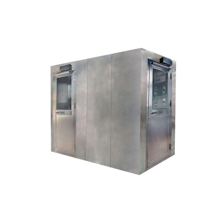
Before site installation, it is necessary to confirm the room pressure gradient, supply and return air margin, floor load capacity, power supply and exhaust pipeline conditions in advance, to avoid failure to reach the designed air volume and negative pressure during equipment commissioning. The weighing booth is generally placed in Grade C or Grade D clean zones, where the room pressure and air change rate shall be stabilized beforehand. For high-activity powder versions, exhaust pipelines are laid independently. The exhaust outlet shall be kept far away from the fresh air intake of the clean air conditioning system, and check valves shall be installed on pipelines to prevent air backflow when the unit stops running.
Leveling of the equipment is fundamental. The overall level deviation shall be controlled within 2 mm/m. The weighing platform is equipped with a shockproof weighing base to prevent fan vibration from being transmitted to the balance and causing weighing errors. The inner cavity is made of SUS304 or SUS316L stainless steel. All welds are fully welded and the inner wall is polished with rounded R-corner transitions to eliminate dust accumulation dead corners. Seals at splicing gaps and flanges shall be continuous, and peel-off adhesive sealing strips are prohibited. Gaps between the outer shell and color steel partition walls are sealed with clean sealant to block bypass air leakage. Special attention shall be paid to the tightness of exhaust pipeline flanges and flexible connections. For high-activity projects, BIBO (Bag-In/Bag-Out) filter structures are adopted. The filter mounting flange surface shall be flat to ensure no bypass leakage during PAO leak testing.
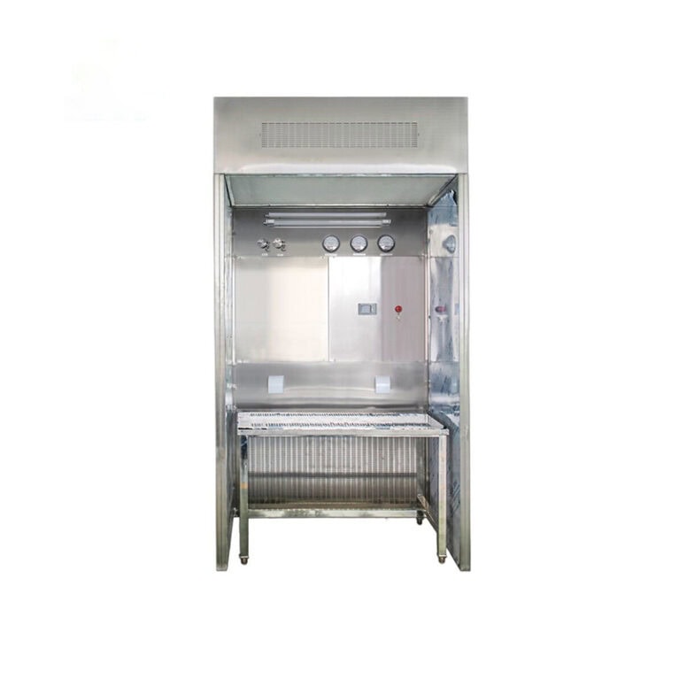
Electrical wiring and monitoring instruments are routed simultaneously. Air velocity sensors and differential pressure transmitters shall not be installed in vortex dead zones or directly exposed to supply/return air jets. Instruments shall be calibrated, and signal cables shall be shielded to reduce signal interference from frequency converters and fans in the workshop. The protection grade of the electrical control box is selected according to cleaning conditions, which shall be no less than IP65 for wet cleaning areas.
2. Specification for Air Velocity Control at Opening Face (Core Indicator for Dust Containment)
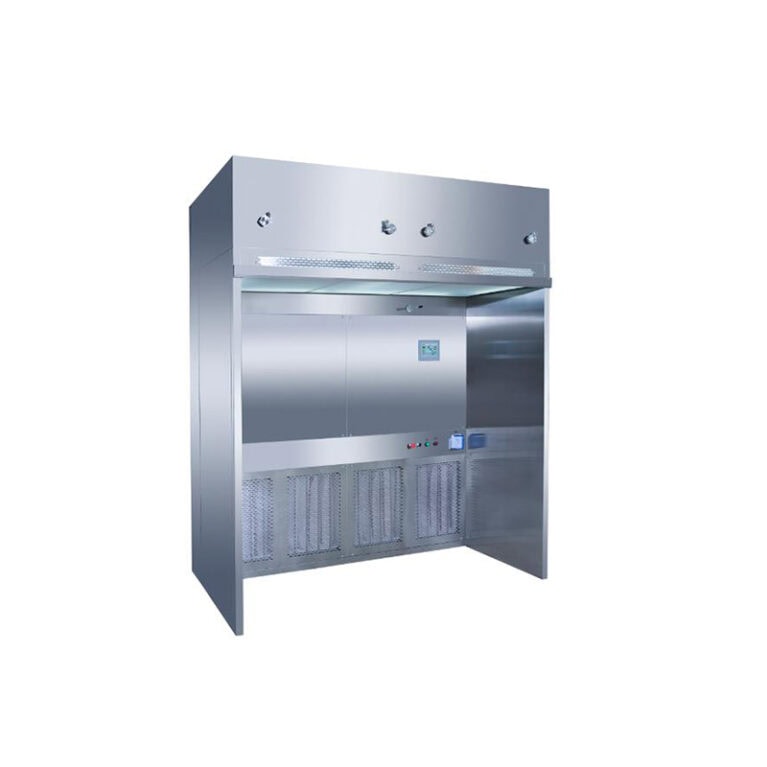
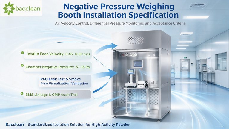
The negative pressure weighing booth forms an airflow barrier by inward intake airflow at the operation window to prevent dust escape. Face velocity is the top priority acceptance indicator. For normal working conditions, the average designed face velocity is controlled at 0.45~0.60 m/s. For high-activity, high-sensitizing and cytotoxic materials, stable velocity above 0.50 m/s is recommended. The general industry acceptance range is 0.36~0.54 m/s, and the uniformity of face velocity across the full opening shall be within ±20% of the average value. Excessive deviation at single points shall be avoided to prevent local negative pressure gaps or turbulent dust re-entrainment.
The velocity measuring points are arranged in a grid layout. The operation opening is divided into uniform grids with side length not greater than 300 mm. Measuring points are located at the center of each grid, and the probe is perpendicular to the plane of the operation window. Tests are carried out under standard operating opening. Data at each point is collected continuously for no less than 60 seconds and the stable average value is taken. The test shall simulate actual operation with operators, balances and material barrels in place; no no-load testing is allowed. Too low velocity will cause dust escape and excessive personnel exposure. Excessively high velocity will disturb powder inside the chamber, resulting in weighing drift and secondary dust flying, while increasing fan load and filter consumption.
Variable frequency fans are used for air volume adjustment to stabilize velocity. Constant air volume control is preferred to automatically compensate air volume as filter resistance rises due to dust accumulation and prevent continuous velocity attenuation. The system shall be equipped with real-time display and audible & visual alarm for face velocity. Upper and lower thresholds are set. Once the velocity drops below the lower limit, an alarm is triggered and weighing operation is locked to prohibit powder handling under failed protection status.
3. Installation Specification for Chamber Negative Pressure and Differential Pressure Monitoring
The weighing chamber maintains stable negative pressure relative to the clean room. The conventional negative pressure setting range is -5 Pa~-15 Pa. The negative pressure value shall not be blindly pursued to be excessively high; it needs to match the face velocity at the opening. The negative pressure monitoring point is set in a stable area inside the chamber away from return air and supply air outlets, and the sensor shall not face direct airflow impact. Differential pressure of supply HEPA and exhaust HEPA is monitored separately to judge filter clogging status.
After installation, differential pressure transmitters must be zero-calibrated under both no-load and loaded conditions and compared regularly with standard differential pressure gauges. The system logic distinguishes two types of alarm signals: chamber negative pressure deviation alarm and high filter differential pressure alarm. Sustained rise of filter differential pressure indicates dust loading and reminds planned replacement. Deviation of chamber negative pressure from the set range suggests pipeline air leakage, fan failure or HVAC imbalance of the room. All differential pressure and air velocity signals can be connected to the workshop BMS system for remote monitoring, alarm recording and data storage to meet GMP audit trail requirements.
During commissioning, coordination with the cleanroom air conditioning system is required to repeatedly verify the influence of weighing booth start-stop on the overall room pressure gradient. The exhaust of the weighing booth shall not cause pressure reversal between adjacent rooms. The check valve on the exhaust pipeline shall close reliably under shutdown status to prevent air backflow into the chamber.
4. Airflow Pattern and Smoke Visualization Acceptance Requirements
Qualified air velocity and negative pressure values do not guarantee qualified airflow. Hidden defects such as vortexes, dead zones and local reverse flow must be checked via smoke visualization test, a mandatory GMP validation item. Smoke release positions cover the weighing table surface, rear part of the chamber and lower edge of the window, where dust is most likely to generate. Smoke shall flow steadily and unidirectionally toward the return air suction port without outward overflow or local recirculation vortex, and shall not stay and accumulate in corners for a long time. The whole test process is video-recorded and retained as PQ qualification documents.
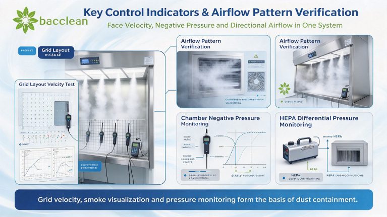
The upper supply HEPA inside the chamber forms vertical laminar flow to maintain ISO Class 5 cleanliness in the operation zone. Downward supply airflow and directional return air suction form a composite airflow mode of “laminar flow + negative pressure enclosure”, balancing internal cleanliness and external isolation. If the smoke test fails, priority checks shall be carried out on whether the flow equalizing membrane and return air deflector are deformed and whether the fan air volume matches, to find local low points of face velocity uniformity.
5. Filter System Installation and PAO Leak Test Specification
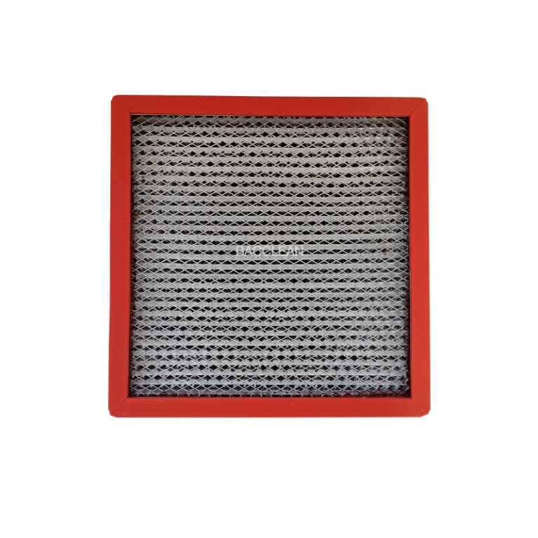
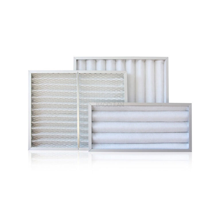
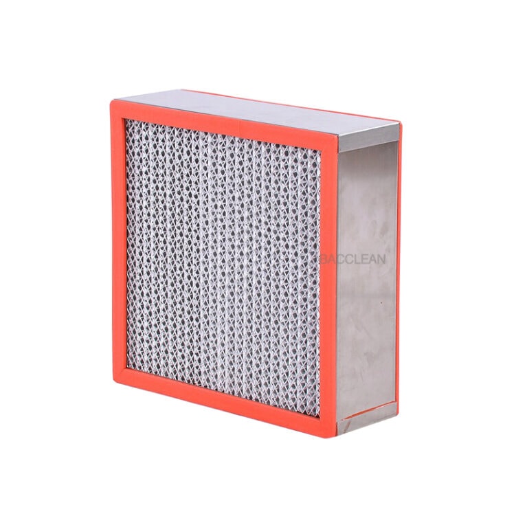
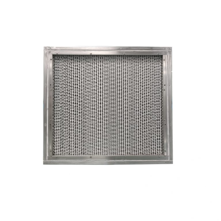
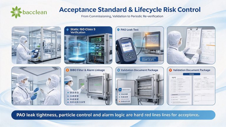
Both supply air and exhaust air of the weighing booth are equipped with independent HEPA filters. H13 grade is adopted for conventional projects, and H14 grade is upgraded for high-activity and high-exposure risk projects. When installing filters, the sealing gasket shall be compressed evenly with consistent stress to avoid leakage caused by unilateral squeezing. PAO aerosol leak test must be performed after installation, using the photometer method. Aerosol is generated stably on the upstream side. The downstream probe scans the entire filter surface, frame, sealing gasket and mounting flange at a scanning speed of 3~5 cm/s, with the probe 2~4 cm away from the filter surface. The acceptance criterion is no leakage point in all areas and leakage rate not exceeding 0.01%.
For BIBO exhaust filters, besides PAO leak testing, the filter replacement procedure shall be verified to ensure no dust escape during replacement. Differential pressure monitoring is used to predict filter service life. When the differential pressure reaches the upper limit, shutdown replacement shall be performed, and leak test must be retested after replacement.
6. Complete Acceptance Items and Acceptance Criteria
Static acceptance can only be carried out after the equipment has run stably for at least 30 minutes, with stable workshop environment, temperature, humidity and room pressure to avoid working condition fluctuations interfering with test results. Particle counting test is sampled at multiple points 200 mm above the weighing table surface. Static status shall meet ISO Class 5: particles ≥0.5 μm ≤3520 pcs/m³, particles ≥5.0 μm ≤20 pcs/m³. Noise acceptance standard ≤65 dB(A) to avoid excessive long-term operating noise in the workshop. Illuminance on the table surface shall be more than 200 lx to meet the requirement for visual weighing reading.
Function acceptance includes alarm linkage test: low air velocity alarm, abnormal negative pressure alarm, high filter differential pressure alarm and fan fault alarm shall be triggered and verified one by one. Power failure and emergency stop functions are tested to confirm that exhaust logic and alarm logic under fault status comply with risk control requirements. For high-activity powder projects, additional dust escape test is carried out. Sampling equipment is used at the outer side of the window and the operator’s breathing zone to assess personnel exposure level.
Document acceptance requires simultaneous delivery of material certificates, stainless steel welding records, instrument calibration certificates, PAO leak test reports, original air velocity / differential pressure test records, airflow smoke videos, together with supporting IQ/OQ documents to support GMP qualification for customers.
7. Common Problems in Installation & Commissioning and Risk Control
The most common problem in the installation phase is only adjusting the total air volume without multi-point grid velocity test, resulting in qualified single-point velocity but weak zones on the opening. Secondly, unreasonable installation position of negative pressure sensors leads to distorted readings and long-term false qualified status. Poor sealing of exhaust flexible connections and flanges gradually causes air leakage under fan vibration, and the protection function fails after a period of use. Some projects ignore HVAC matching of the room. Insufficient supply air volume of the workshop causes the overall room pressure gradient to collapse due to continuous exhaust of the weighing booth.
After commissioning, fan frequency conversion parameters, air velocity alarm thresholds and negative pressure set values shall be locked by permission. On-site operators are prohibited from modifying them arbitrarily. A periodic reconfirmation schedule shall be established. Daily inspections focus on alarm records and differential pressure trends. Face velocity and airflow pattern shall be retested regularly, and HEPA leak test shall be retested at least once a year.
Resumen
The core logic for negative pressure weighing booth installation is to take the intake face velocity at the opening as the barrier, chamber negative pressure as isolation, stable directional airflow for dust control, and air velocity & differential pressure instruments for continuous monitoring. During installation, leveling and sealing, independent exhaust and instrument calibration shall be completed. In the commissioning phase, room HVAC balance, grid velocity calibration and smoke flow pattern verification shall be performed synchronously. For acceptance, PAO leak test, particle counting, alarm linkage and dust escape assessment are taken as hard red lines. Bacclean provides standardized solutions covering factory production, on-site installation and validation delivery. BIBO versions for high-activity applications and data traceability docking are supported to meet GMP audit and occupational protection requirements for pharmaceutical enterprises.
