
1. Main Frame and Body Structure
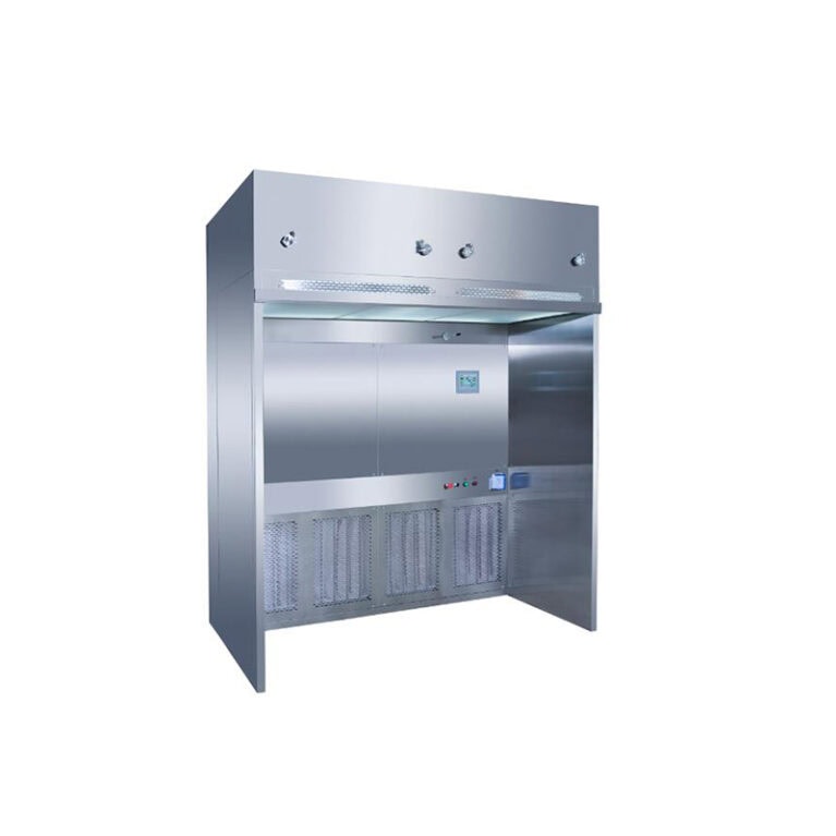
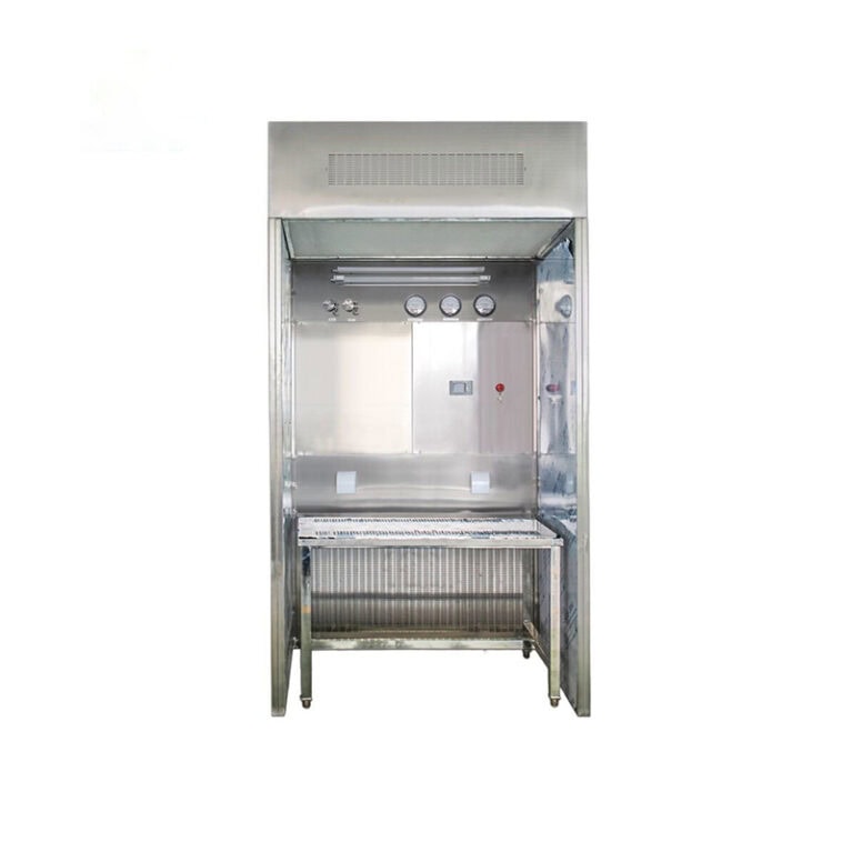
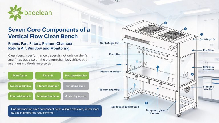
The outer shell of a vertical flow clean bench is generally made of cold-rolled steel with powder coating or 304 stainless steel. Stainless steel models resist acid and alkali and are easy to clean and disinfect, which is more suitable for pharmaceutical and microbiology laboratories. The whole cabinet is roughly divided into three sections: upper plenum chamber, middle working zone and lower return air zone. The worktop is an integrated stainless steel surface with seamless finish for easy wiping and disinfection. Some models are equipped with anti-slip diversion grooves to collect waste liquid generated during operation. A transparent viewing window (acrylic or tempered glass) is installed on the front, which can be lifted up and down with a limit device to control the opening height and prevent massive airflow overflow that would damage the internal laminar flow. Sleeve ports or open operation ports are arranged on both sides of the operation opening. Some units are fitted with UV germicidal lamps to disinfect the chamber when not in use.
2. Fan Unit: Power Source of Airflow
The fan supplies power for vertical flow benches. Centrifugal fans or direct-drive FFU fans are mainstream options. Early models mostly adopted centrifugal fans, while new vertical flow benches increasingly use integrated FFU fan modules. The fan draws return air, boosts static pressure and sends steady airflow into the upper plenum chamber to provide continuous and stable air volume for the whole laminar system. Key parameters for fan selection include static pressure, air volume, noise and speed regulation performance. HEPA filters have certain airflow resistance, so the fan must deliver sufficient static pressure to overcome filter and duct resistance, keeping the average wind speed of the air outlet within the standard range (normally 0.36~0.54 m/s). Most fans are equipped with variable frequency speed control for wind speed adjustment. As dust accumulates on filters, resistance rises gradually and wind speed drops for fixed-speed fans. Models with differential pressure feedback or frequency conversion compensation can automatically adjust fan speed to stabilize wind speed. Fans are usually installed above the plenum chamber or in the return air section. Shock-absorbing pads are fitted during installation to reduce vibration transmission to the cabinet, lowering running noise and table vibration that may interfere with precision experiments. Fan vibration is a hidden risk for clean benches. Long-term vibration will crack the filter sealing adhesive and cause air leakage, so shock absorption is a critical detail for fan installation.
3. Filter System: Barrier for Cleanliness
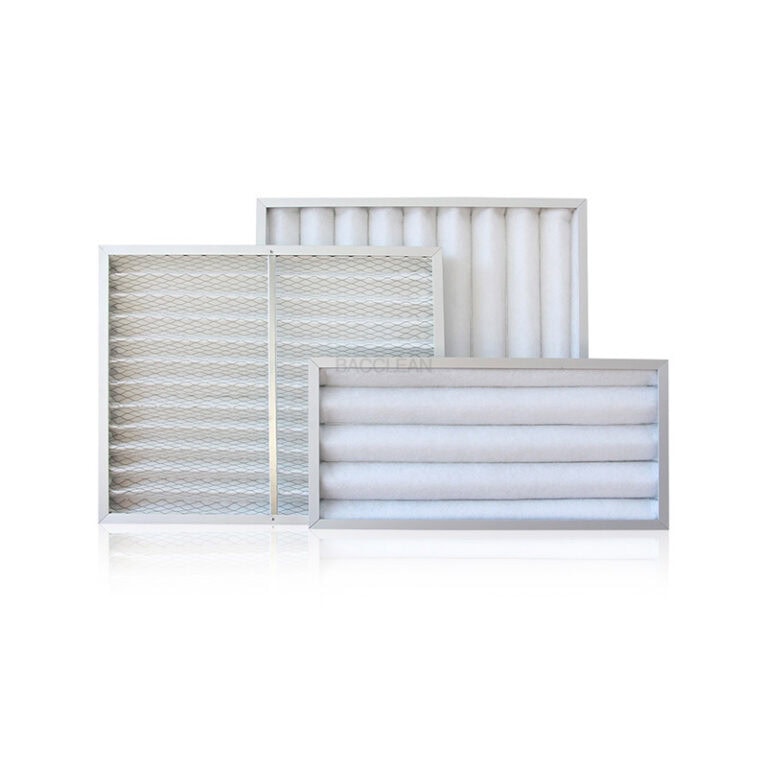
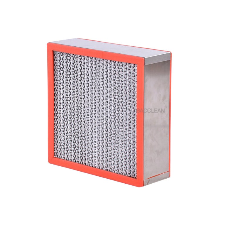
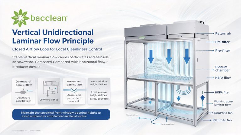
The filtration system of vertical flow clean benches normally adopts a two-stage series configuration: pre-filter + HEPA filter with separate responsibilities.
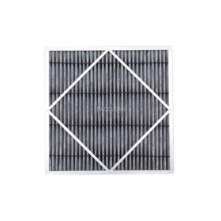
- Prefiltro: Installed at the lower return air inlet as the first barrier. It intercepts large dust particles, fibers, hair and other pollutants to protect the downstream HEPA filter, reduce dust load and extend HEPA service life. Pre-filters are mostly made of non-woven fabric or plate filter media. They have short replacement cycles and low maintenance cost, which is the key component for routine maintenance.
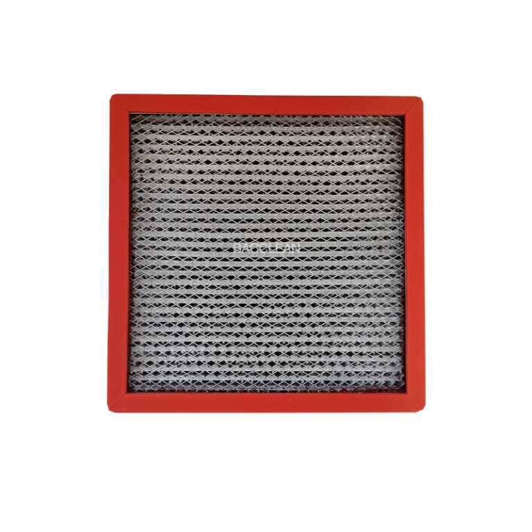
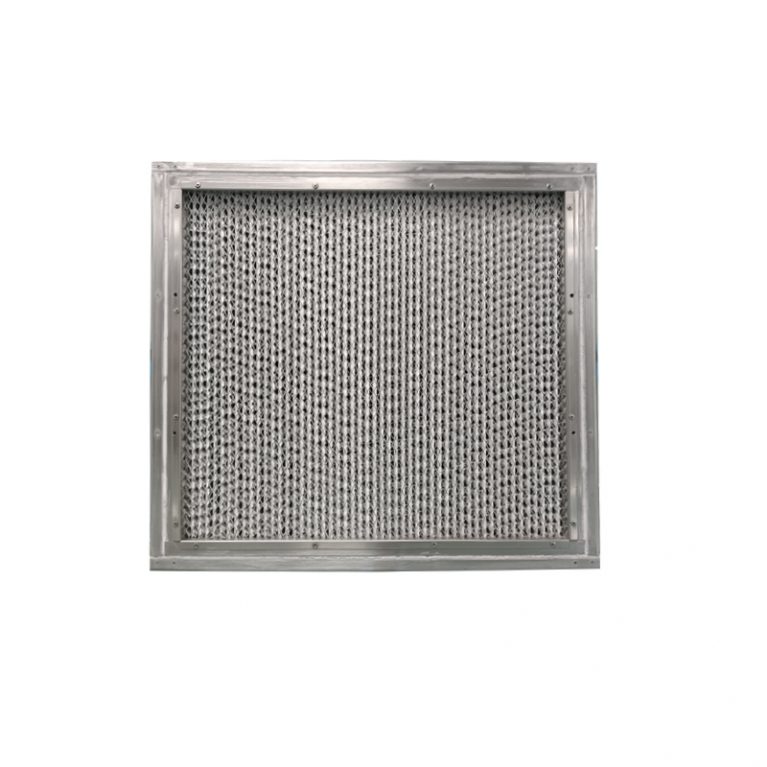
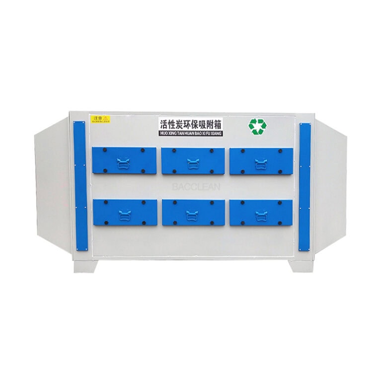
- Filtro HEPA: Mounted under the plenum chamber directly above the working zone, it is the core filter component of the bench. H13 and H14 grades are commonly selected according to cleanliness requirements. After pressure stabilization in the plenum chamber, airflow passes evenly through the HEPA filter. Submicron particles are captured inside the filter media via diffusion, inertial impaction and interception. Sealing adhesive or liquid tank sealing structure is used between the filter and plenum chamber to avoid bypass air leakage from frame gaps. PAO leak test must be carried out during equipment acceptance and periodic validation to check for media damage and seal leakage. Some special models for samples with chemical odors are additionally equipped with activated carbon filters to adsorb organic gas. However, activated carbon modules cannot filter particulate matter and cannot replace HEPA filters.
4. Plenum Chamber and Flow Equalization Structure: Key to Uniform Airflow
The plenum chamber is often overlooked. It acts as the intermediate cavity connecting the fan and HEPA filter. Airflow delivered by the fan is turbulent and uneven. If blown directly onto the filter, it will lead to uneven velocity across the filter surface and destroy laminar flow. When airflow enters the enclosed plenum chamber, dynamic pressure converts into static pressure. Airflow slows down and pressure distributes evenly inside the chamber, then flows downward uniformly across the entire cross-section of the HEPA filter. Some benches add diversion plates and flow equalization membranes above the filter to further optimize airflow distribution, control wind speed deviation within allowable limits and avoid local vortex.
5. Airflow Organization Principle (Vertical Unidirectional Laminar Flow)
The core feature of vertical flow clean benches is vertical unidirectional laminar airflow. The closed airflow cycle is as follows: Fan extracts return air at the bottom → Airflow passes through pre-filter for preliminary purification → Enters the top plenum chamber for pressure stabilization → Flows vertically and evenly through the HEPA filter → Forms parallel, stable clean laminar flow covering the whole working surface → Carries particulate contaminants generated during operation back to the return air duct from both sides or bottom of the tabletop, then circulates back to the fan. Under ideal conditions, airflow streamlines are parallel without vortex or backflow. Continuous clean airflow covers the operation area and carries dust and aerosol generated during operation downward, preventing contaminants from suspending in the working space. This is the advantage of vertical flow over horizontal flow: airflow does not blow directly toward the operator’s face, lowering the spread risk of microbial and sample aerosols. One critical boundary condition: the front window opening height directly affects airflow organization. An excessively high opening easily induces entrainment of unfiltered ambient air into the working zone and invalidates cleanliness. An overly low opening hinders operation. The standard opening height marked by manufacturers is a safe range determined by airflow simulation. Once vortex forms, contaminants accumulate in swirling areas, resulting in excessive particle counts locally even if the filter is intact.
6. Control and Monitoring Accessories
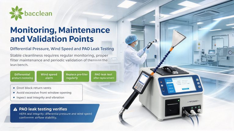
Electrical accessories guarantee stable airflow operation: wind speed sensors, differential pressure gauges, main control boards and audible & visual alarms. Differential pressure gauges monitor the pressure difference upstream and downstream of the HEPA filter. Sustained pressure rise indicates heavy dust accumulation. The system will prompt filter replacement when reaching the final resistance limit. Wind speed sensors collect real-time airflow velocity inside the working zone and trigger alarms at low wind speed to remind operators to inspect fans and filters.
7. Summary of Operation and Maintenance Tips
Stable airflow organization relies on proper equipment design as well as daily operation and maintenance. Clean or replace pre-filters regularly to reduce HEPA load; record HEPA differential pressure periodically and replace filters on time. PAO leak test and wind speed uniformity test must be completed after HEPA replacement to confirm airflow organization is intact. Do not block return air vents during operation, as blocked return air leads to air volume attenuation and laminar flow disorder.
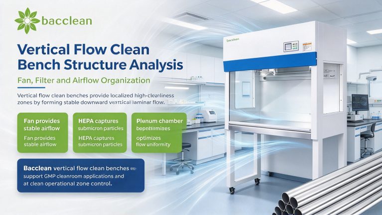
In summary, the fan provides power, the filter captures particulates, and the plenum chamber plus duct layout form stable vertical laminar airflow. The three parts work together to maintain a high-cleanliness environment inside the open window. A vertical flow clean bench is more than a simple combination of fan and filter. The design of pressure stabilization, flow equalization and closed return air loop directly determines the cleanliness stability in practical use, which is a key focus during selection and validation.
