
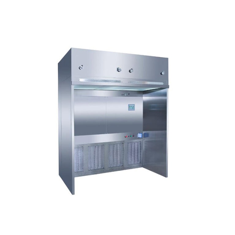
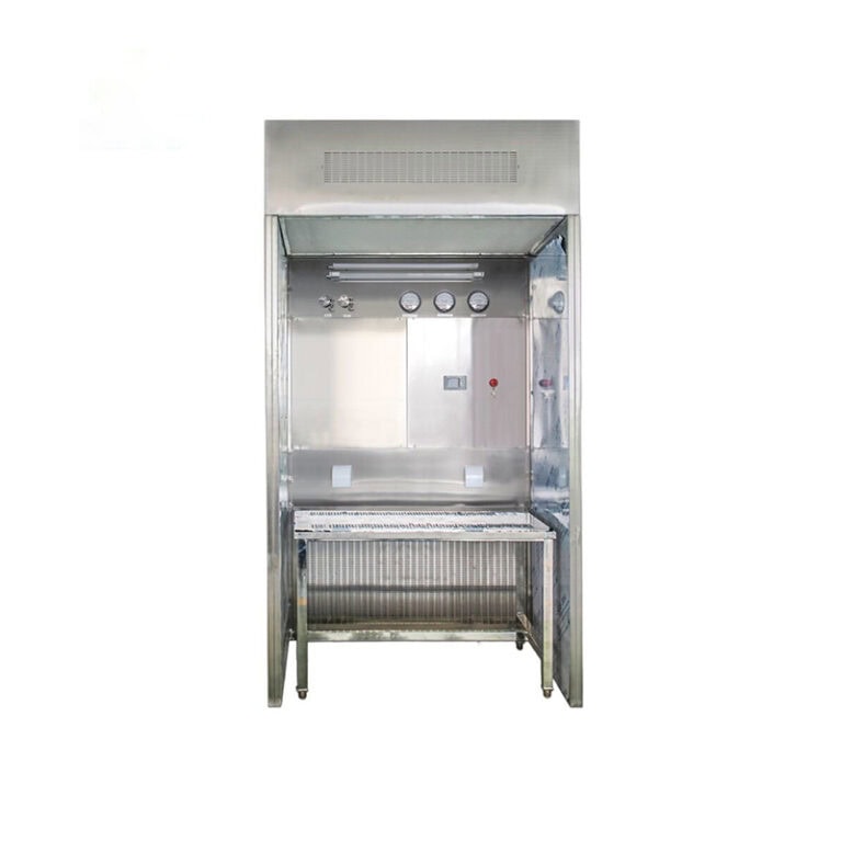
Different from ordinary HEPA supply air outlets which deliver air at discrete points, it supplies uniform air across a large continuous surface. It relies on “piston-type” downward airflow to continuously push particulate and microbial contaminants to the return air openings below for discharge, preventing cross-contamination caused by turbulent transverse airflow.
1. Working Principle
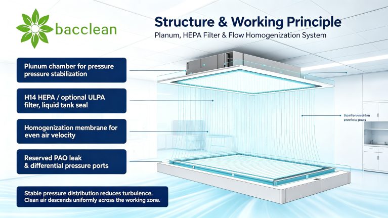
Treated air from the central air conditioning system is fed into the plenum chamber of the laminar flow ceiling. The large-volume cabinet stabilizes airflow and eliminates air pressure fluctuations. After deep filtration by HEPA / ULPA filters, the air passes through a flow homogenization membrane or perforated flow equalization plate for secondary flow conditioning, then discharges vertically downwards in evenly distributed parallel streamlines. The airflow velocity across the entire air outlet surface has minimal deviation, forming a stable unidirectional flow protection zone. Contaminants cannot suspend or spread within the critical area; they are continuously displaced and carried away by airflow, creating a locally ultra-clean zone beneath the ceiling.
Many practitioners confuse laminar flow ceilings with standard HEPA supply outlets. Ordinary HEPA diffusers supply air at single points. Their airflow tends to diverge and generate turbulence, suitable for non-unidirectional clean rooms of Grade C / D. Laminar flow ceilings feature large-area uniform air supply, designed specifically to maintain unidirectional flow and meet requirements for high-grade local protection — this is their most essential distinction.
2. Basic Structural Composition
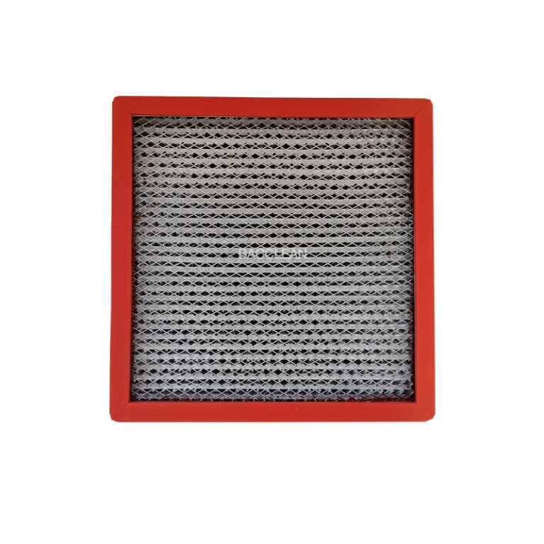
A complete laminar flow ceiling assembly mainly consists of a plenum box, sealing frame, high-efficiency filter, flow homogenization component, leak test port and differential pressure monitoring port.
- The plenum box acts as the core pressure stabilizer, ensuring consistent air pressure supplied to every filter unit and avoiding local over-speed or under-speed airflow.
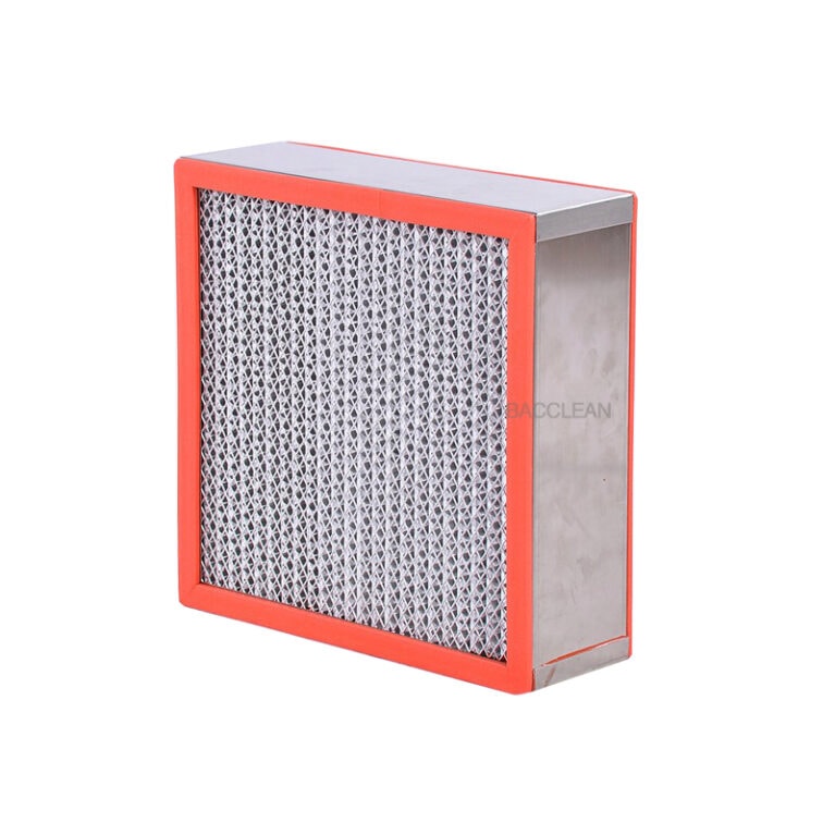
- Filtration units generally adopt H13 / H14 grade HEPA filters. ULPA ultra-high-efficiency filters are selected for ultra-high-standard scenarios. Liquid tank gel sealing is widely used to reduce bypass leakage at the filter frame, supporting GMP validation and PAO aerosol leak testing.
- The lower flow homogenization layer (leak-resistant layer, homogenization membrane or perforated plate) is critical for laminar performance. It breaks down airflow eddies and ensures uniform velocity across the full air outlet surface.
- Cabinet material is normally 304 stainless steel. 316L stainless steel is preferred for pharmaceutical and operating room environments with frequent disinfection and corrosive sanitizers. Inner walls adopt rounded transitions to eliminate dust accumulation dead corners and facilitate wiping and disinfection.
- Ports for differential pressure measurement and aerosol leak testing are reserved for subsequent validation and periodic inspection.
3. Main Application Scenarios
- Pharmaceutical Industry: Aseptic filling, capping, aseptic dispensing and protection zones integrated with isolators. EU GMP Annex 1 defines clear requirements for unidirectional flow in aseptic core zones. Laminar flow ceilings maintain Grade A clean environments above critical process points to control risks from active pharmaceutical ingredients and microbial contamination.
- Medical Clean Operating Rooms: Standard configuration for Class I clean operating rooms. Installed above the surgical field to protect the operation area and reduce post-operative infection risks, also deployed in laminar flow wards and transplant wards.
- Microelectronics, Semiconductors and Optics: Wafer inspection, chip packaging and optical lens assembly. Low-outgassing, silicone-free low-particle-emission versions are available for zones sensitive to particulates and AMC molecular contamination to build local ISO Class 5 protection.
- Precision Laboratories, Animal Facilities and Medical Device Workshops: Aseptic testing, cell culture and sterile medical device assembly requiring localized high-level clean isolation.

Its design logic is local high-grade protection. Instead of upgrading the whole room to Class 100, laminar flow ceilings are only arranged above high-risk, process-sensitive positions, balancing purification performance and project cost.
4. Core Selection Parameters
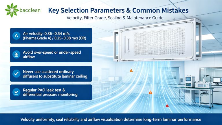
- Air supply surface velocity: 0.36–0.54 m/s is commonly specified for Grade A pharmaceutical zones; 0.25–0.38 m/s for Class I operating rooms. Velocity uniformity is a key acceptance indicator. Deviation across the full surface must stay within specification limits. Excessive local velocity causes noise, while insufficient velocity fails to counteract upward thermal plumes generated by personnel and equipment, breaking the laminar protection layer.
- Filter Class: H14 HEPA for conventional projects; ULPA for semiconductor and ultra-high-cleanliness applications. Liquid tank sealing is preferred over gasket sealing, with slower aging and lower leakage risk under repeated disinfection cycles.
- Dimension Specification: Customized according to the size of the protected process area, mostly modular rectangular designs. Layout must avoid lights, hangers and obstacles to keep the air supply surface intact and prevent airflow short-circuiting.
- Material and Particle Emission Control: Stainless steel is prioritized for pharmaceutical and medical use. Electronic projects require strict control over sealants and damping materials, specifying low-volatility, silicone-free, low-shedding formulations.
- Monitoring Accessories: Differential pressure gauges track filter resistance rise to predict clogging. PAO leak test ports are reserved for IQ/OQ validation and periodic leak inspection.
5. Common Design & Operation Pitfalls
- Misconception: Higher velocity always means better performance. Excessive airflow increases noise, disturbs airflow, creates discomfort for operators and entrains surrounding low-clean air. If velocity is too low, thermal plumes from human heat dissipation rise and penetrate the laminar protective layer.
- Misconception: Multiple ordinary supply diffusers can replace a laminar flow ceiling. Airflows from separate outlets interfere with each other and form chaotic streamlines. Stable unidirectional flow cannot be achieved, making it difficult to consistently pass particle count acceptance tests.
- Misconception: Neglect surrounding layout. Tall heat-generating equipment cannot be placed directly under the laminar protection zone. Return air arrangement, room pressure cascade and personnel workflow must coordinate with airflow organization. Even high-quality laminar flow ceilings will fail to deliver expected results without proper layout.
Key maintenance practices: Record filter differential pressure regularly and replace filters once pressure exceeds threshold; perform periodic PAO leak tests to check for cracking and leakage of liquid tank seals; wipe cabinet surfaces to prevent dust buildup; avoid impact and damage to the homogenization membrane, as damage directly triggers airflow turbulence.
Conclusion
A laminar flow ceiling serves as a local unidirectional flow terminal in cleanroom engineering. Its core value is not upgrading the whole cleanroom, but establishing a stable downward clean airflow barrier precisely over critical process zones. Overall performance depends not only on filter grade, but also on plenum pressure stabilization design, homogenization structure, sealing reliability and velocity uniformity. Air velocity testing, filter leak inspection and airflow visualization are mandatory validation items for laminar flow ceilings under GMP and ISO14644 projects. Proper selection, professional installation and standardized maintenance are essential to reliably defend the contamination control baseline for high-cleanliness processes.
