
I. Pre‑installation Inspection
Installation shall commence only after air ducts and ceiling plenum compartments have been fully cleaned and the air‑conditioning system has been purged and commissioned to pass acceptance. Filter unpacking shall be performed exclusively inside the cleanroom, and all outer packaging shall be removed out of the clean zone to prevent filter media contamination.
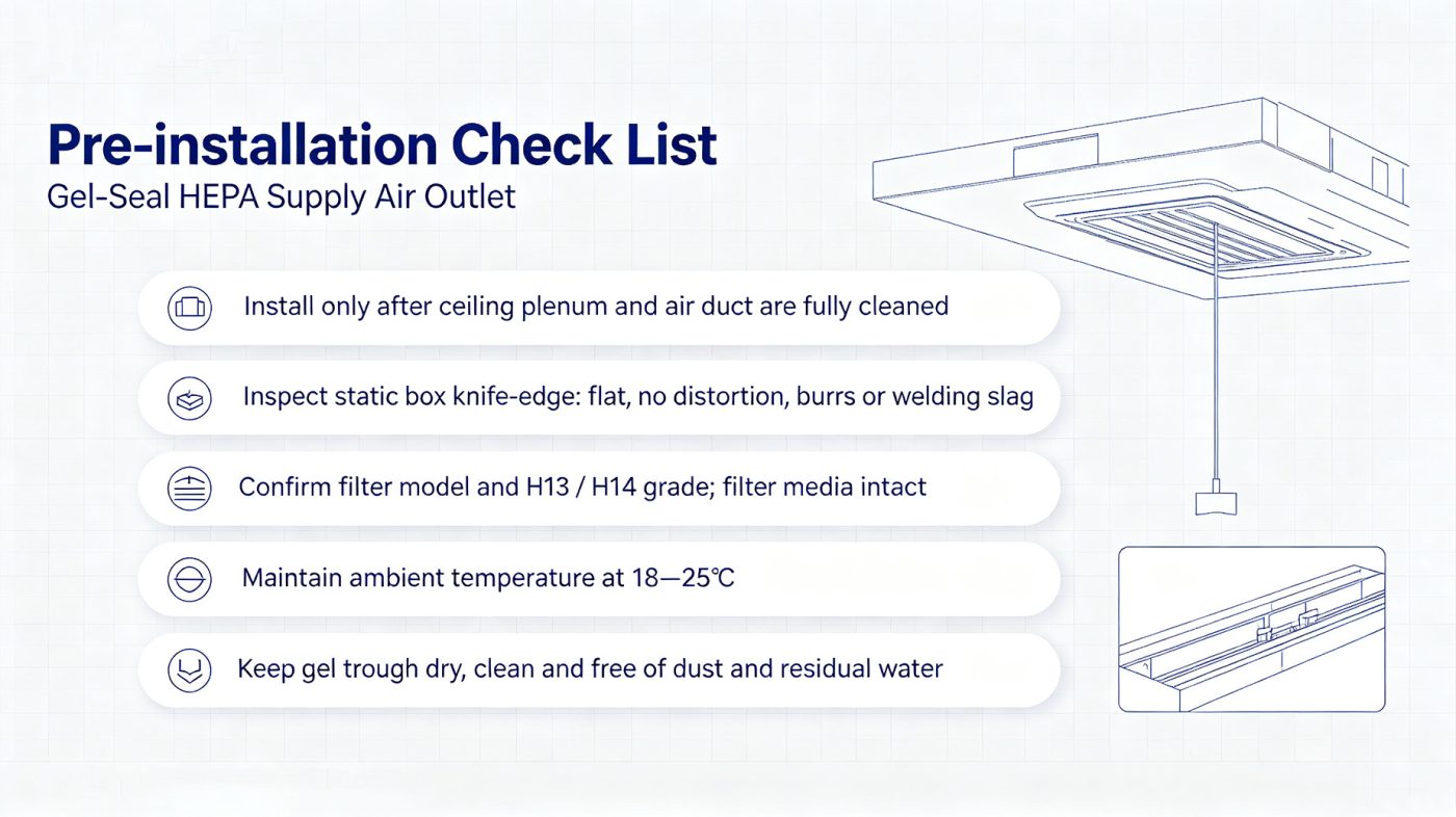
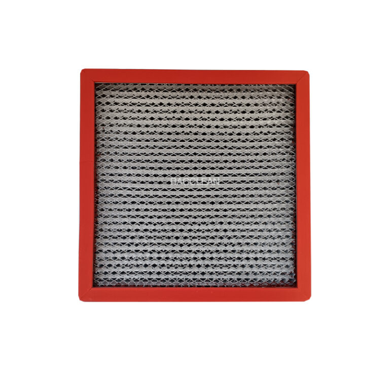
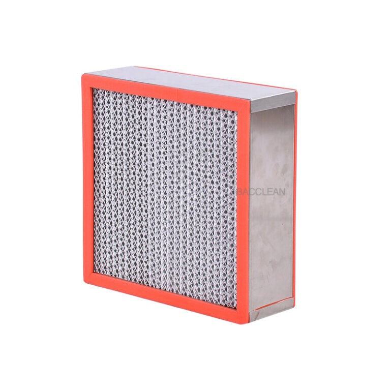
Verify model, specification and filter class (H13/H14). Inspect the static pressure box welds and gel‑seal knife edge: the four sides of the knife edge shall be flat, corner welds shall be smoothly ground free of welding slag, burrs, distortion or twisting. Flatness of the knife edge shall be ≤ 2 mm per metre. A deformed knife edge will directly cause sealing leakage and shall NOT be forcibly compensated by compression blocks.
Examine filter appearance: no damage to filter paper and no dents or deformation on the filter frame. Confirm that the airflow arrow on the filter points toward the static pressure box (upward); reverse installation is strictly prohibited.
Maintain on‑site ambient temperature at 18‑25 °C and relative humidity at 40‑60 %. Low temperature will harden gel and degrade sealing performance. The gel trough must be free of water, dust and disinfectant residues; wipe and thoroughly dry the trough prior to gel pouring.
II. Hoisting of Static Pressure Box on Ceiling and Duct Connection
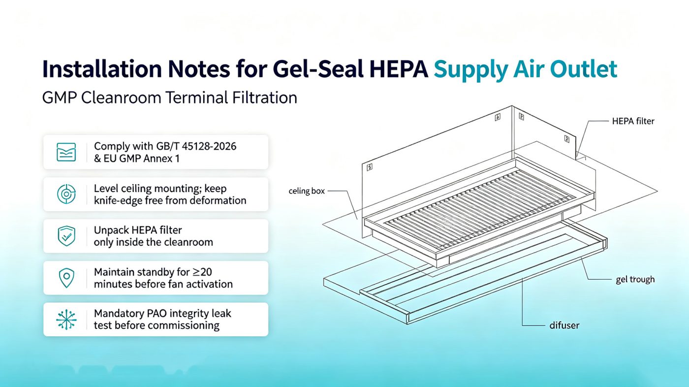
Secure suspension rods firmly to building load‑bearing structures and level the box with a horizontal deviation ≤ 2 mm/m. Tilted box will cause uneven gel liquid level inside the trough, resulting in insufficient local immersion depth of the knife edge and concealed leakage points.
For top‑connected / side‑connected air duct flange joints, apply neutral silicone sealant to flange gaps to eliminate bypass air leakage. Seal all internal and external welds and assembly joints of the box.
Apply continuous sealant at the joint between supply‑air‑outlet flange and ceiling panel to prevent unfiltered plenum air from infiltrating into the clean zone.
For unidirectional‑flow areas, match filters of the same batch by resistance. The resistance deviation of each filter against the average resistance shall preferably be less than 5 % to guarantee uniform air supply.
III. Key Points for Gel Potting (Core of Sealing Performance)
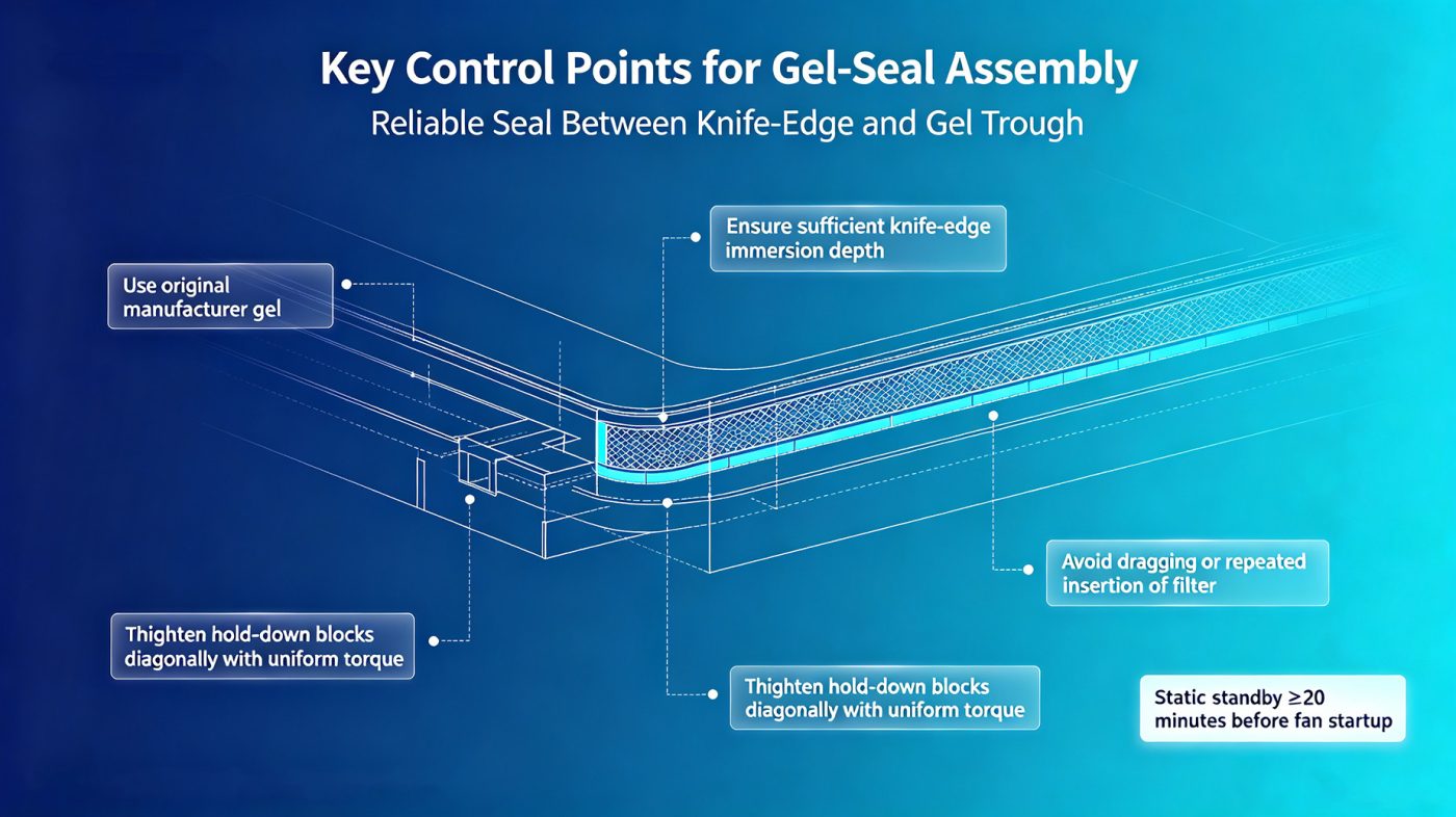
Use only original OEM matching gel. Mixing gels from different brands is forbidden, as chemical reaction may occur and cause delamination and sealing failure.
Thoroughly stir and defoam the gel before pouring into the trough. Fill to 70 %‑80 % of trough depth to ensure knife‑edge immersion depth ≥ 15 mm. No air bubbles shall remain in the gel, since bubbles will form leakage pathways.
Allow poured gel to stand and cure under stable temperature and humidity conditions; fit filters only after gel stabilises.
When replacing old filters, completely remove aged residual gel from the trough, wipe the trough with isopropyl alcohol and allow full drying before fresh gel pouring. Do not simply pour new gel on top of old residual gel.
IV. Installation of Gel‑Sealed Filter (High‑frequency GMP Non‑conformance Points)
Large‑size filters require two‑person handling. Wear clean‑room gloves, handle with care, lower vertically for one‑step positioning. Tilting, lateral dragging and repeated insertion‑removal of filters are prohibited; repeated insertion‑removal will tear the gel and result in permanent sealing defects.
Ensure the full four‑sided knife edge of the filter is immersed in gel with no partial suspension or single‑side lifting.
Tighten compression blocks diagonally and evenly with torque controlled at 8‑10 N·m. Heavy‑handed single‑side tightening shall be avoided; it will warp the filter frame, collapse filter media and cause seal failure.
After filter installation, enforce a standing period of no less than 20 minutes before fan startup. Immediate fan operation post‑installation will agitate gel by airflow impact and create gap leakage leading to failed PAO leak testing.
V. Differential‑pressure / PAO Test Ports and Diffuser Plate Installation
Correctly route differential‑pressure sampling tubing and connect external differential‑pressure gauge; record initial filter resistance. Tubing shall be free of kinks and air leakage.
Verify unobstructed PAO aerosol injection and sampling ports on the static pressure box; cap idle ports tightly. Ensure port sealing gaskets are properly seated to avoid port‑side air leakage which compromises leak‑test results.
Fit diffuser plates securely and tighten screws evenly. Prevent deformation and collision against filter media.
VI. System Commissioning and PAO Integrity Leak Test (Mandatory GMP Acceptance Item)
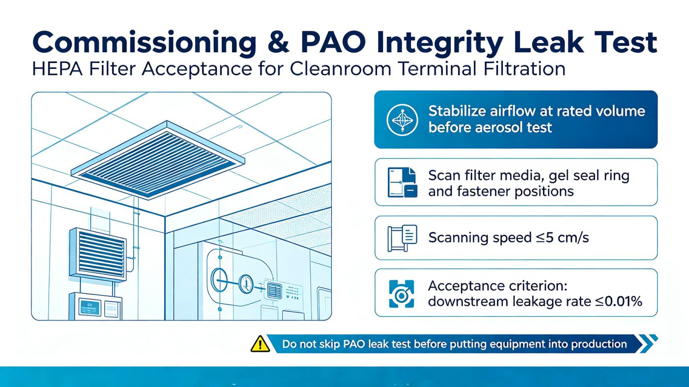
Perform PAO aerosol leak test only after the HVAC system runs stably at rated air volume.
Carry out comprehensive scanning covering filter media surface, filter frame, gel‑seal knife‑edge interface and four‑corner compression‑block positions. Scanner traverse speed shall be ≤ 5 cm/s.
For H14 filters, downstream leakage rate ≤ 0.01 % is deemed acceptable. If leakage occurs, re‑position the filter first. Replace the filter if retest still fails; never simply cover leaks with sealant.
Production can commence only upon passing leak test. Skipping PAO leak test before production will be regarded as a major deficiency during GMP audit.
VII. Common Installation Prohibitions (Pitfall‑avoidance Checklist)
❌ Install ceiling‑mounted boxes out‑of‑level, use compression blocks to force‑compensate distorted knife edges
❌ Pour gel without defoaming and leave entrapped air bubbles
❌ Fit filters with tilting, drag laterally or repeatedly insert‑remove to tear gel
❌ Tighten compression blocks heavily on one side and cause uneven stress
❌ Start fans immediately after filter mounting without required standing time
❌ Mix gels of different brands or batches
❌ Hand‑over for use without PAO leak test
❌ Reverse‑mount filters with wrong airflow direction
VIII. Operation & Maintenance Related Notes
Perform PAO integrity test at least once per year for Grade A/B clean areas.
Replace filters promptly when resistance rises to twice the initial resistance.
For VHP fumigation environments, select VHP‑resistant gel. Prevent direct contact of gel with highly corrosive disinfectants.
