Due to the fact that the environmental sensitivity of semiconductor processes (such as advanced 7nm and 5nm processes) increases exponentially as the process shrinks, the standards for cleanrooms are much higher than those for ordinary industrial or medical clean environments. The specific requirements can be broken down into the following six core dimensions:
I. Air Particle Control: The core of the core
In semiconductor manufacturing, even a particle with a diameter of less than 0.1μm (approximately 1/500 the diameter of a human hair) adhering to the surface of a wafer may lead to the scrapping of the chip. Therefore, particle concentration is the core basis for cleanroom classification. The industry generally follows the international standard ISO 14644-1 (Air Cleanliness Classification), but the actual standards implemented in the semiconductor industry are usually much higher than the general level.
1. The cleanliness classification is matched with semiconductor applications
ISO 14644-1 uses “the number of particles ≥ a specific particle size per cubic meter of air” as the classification index. The semiconductor industry mainly uses ISO Class 1 to Class 5 (while ordinary industrial cleanrooms are mostly Class 8 to Class 9), and different processes correspond to different levels:
| Cleanliness class (ISO 14644-1) | Core control particles (particle size) |
Maximum particle count per cubic meter |
Typical semiconductor application scenarios |
| Class 1 | 0.1μm、0.2μm | 0.1μm: ≤1 piece; 0.2μm: ≤0 pieces | Advanced processes of 5nm and below (such as EUV lithography, wafer bonding) |
| Class 2 | 0.1μm、0.2μm | 0.1μm: ≤2 pieces; 0.2μm: ≤1 piece | 7-14nm processes (such as etching, thin film deposition) |
| Class 5 | 0.1μm、0.5μm | 0.1μm: ≤1000 pieces; 0.5μm: ≤29 pieces | Mature processes of 28nm and above (such as cleaning and diffusion) |
2. Particle source control
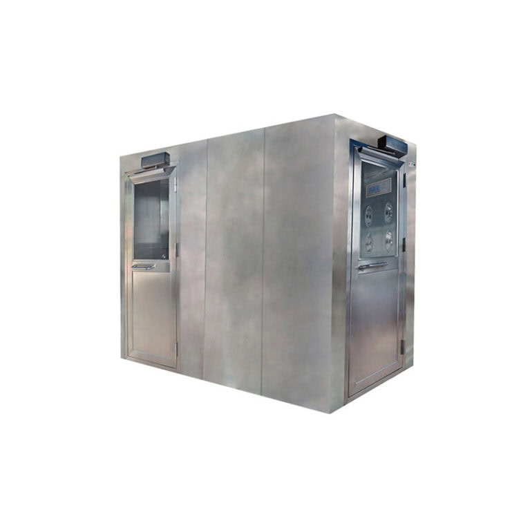
Personnel are the largest particle source (each person generates 1–10 million particles per minute). They must wear dust-free suits, masks, gloves, and shoes. Before entering the clean room, they pass through an air shower (high-pressure airflow to remove particles) and an air lock room (to balance pressure and block external air).
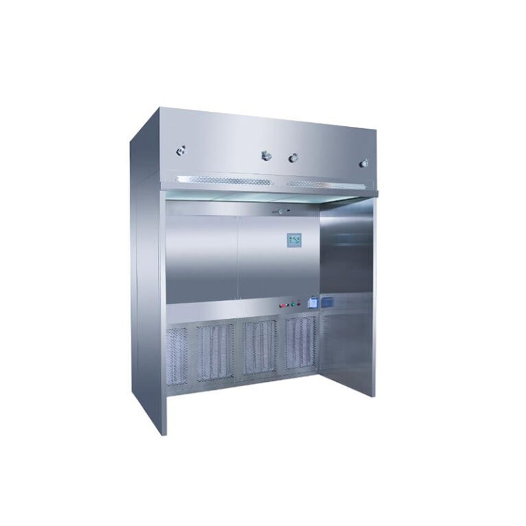
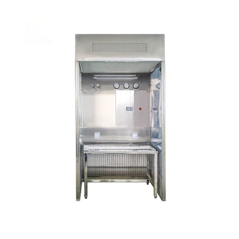
Production equipment (like photolithography and etching machines) must have a local clean unit to contain particles during operation. Seal equipment connections to the floor and walls to stop dust buildup.
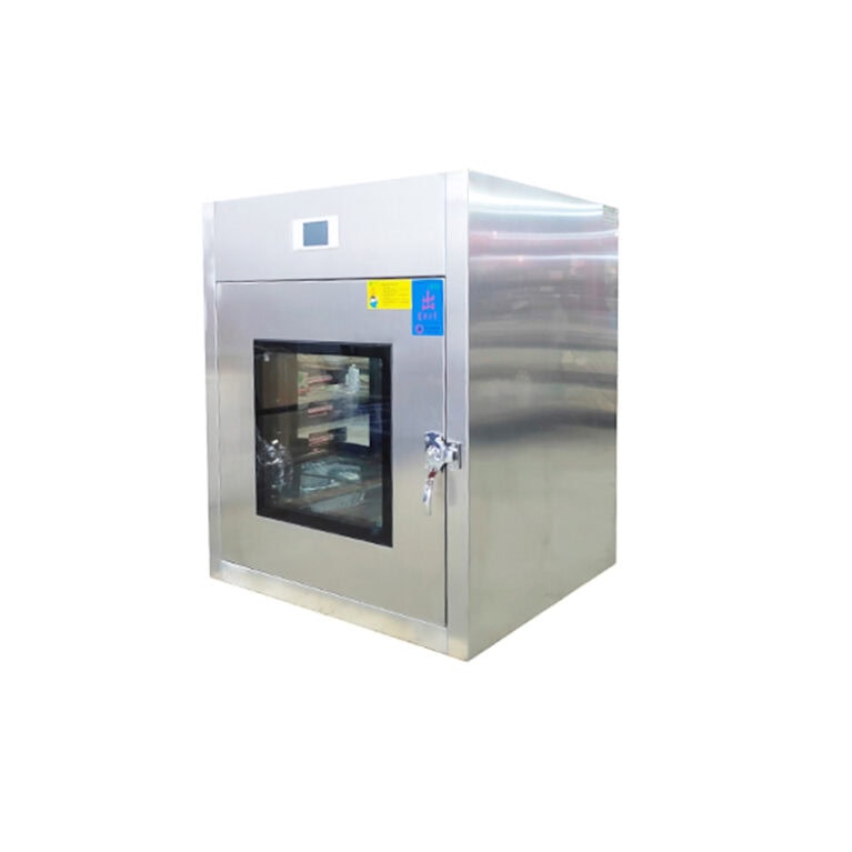
Material control: Wafers, photoresists, and other materials need to enter the clean room through the “dust-free transfer window” (with ultraviolet disinfection and air flow purification), and the outer packaging needs to be removed and cleaned outside the clean room. The material transport trolley should be equipped with a brushless motor (to prevent carbon powder from falling off), and the wheels should be made of anti-static and dust-free materials.
Ii. Temperature and Humidity Control: Micron-level precision requirements
Semiconductor processes, like photolithography and thin film deposition, are very sensitive to temperature and humidity changes. Temperature fluctuations can cause wafer expansion or contraction, affecting alignment (e.g., a 1℃ change causes a 0.1μm deviation). Humidity changes can affect photoresist or metal film adhesion and cause static electricity buildup.
1. Temperature control
Control range: Generally, it is required to be 23℃±0.1℃ to ±0.5℃ (±0.1℃ for advanced processes, and ±0.5℃ for mature processes), and the temperature difference between different areas in the clean room (such as the photolithography area and etching area) should be ≤0.3℃.
Control mode: The “constant temperature and Humidity air conditioning System (MAU+AHU)” is adopted. The temperature is monitored in real time through precision sensors, and it is regulated in combination with variable frequency fans and electric heating/cold water coils to ensure uniform air flow temperature (avoiding local hotspots).
2. Humidity control
Control range: Generally, a relative humidity (RH) of 45%±5% is required (for some processes, such as aluminum metallization, RH≤30% is needed to prevent aluminum oxidation; for photolithography processes, RH stability is required to avoid moisture absorption of the photoresist).
Control method: Reduce humidity through a dehumidifier (rotary dehumidification or refrigeration dehumidification), or adjust humidity through steam humidification (using purified water to avoid impurities in the water from entering the air), ensuring that the humidity fluctuation is ≤2% per hour.
Iii. Airflow Organization: Unidirectional flow is dominant to avoid dead corners
The airflow design of a cleanroom must ensure that “particles are continuously discharged and do not remain or circulate above the wafers”. The core mode is vertical unidirectional flow (laminar flow), while some auxiliary areas adopt “horizontal unidirectional flow” or “non-unidirectional flow (turbulent flow)”.
Vertical unidirectional flow (core production area)
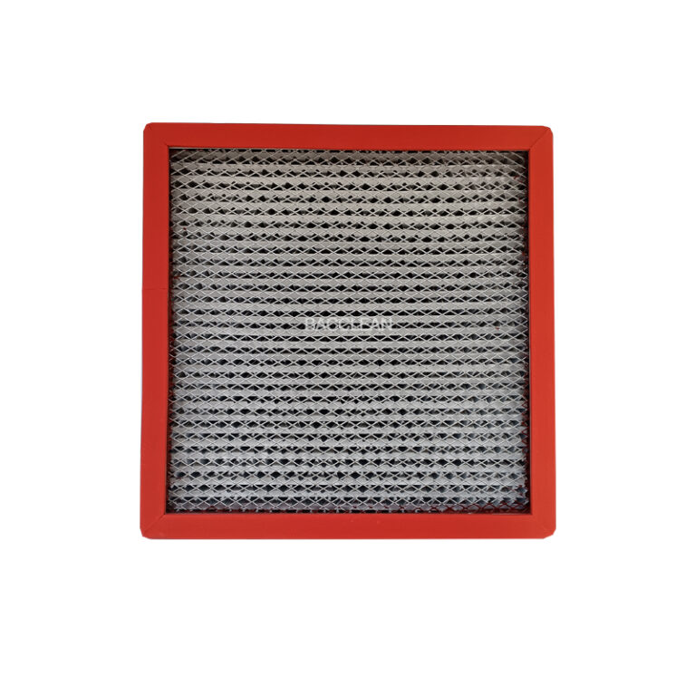
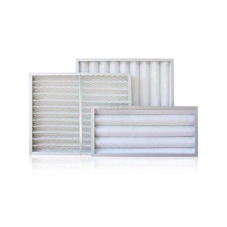
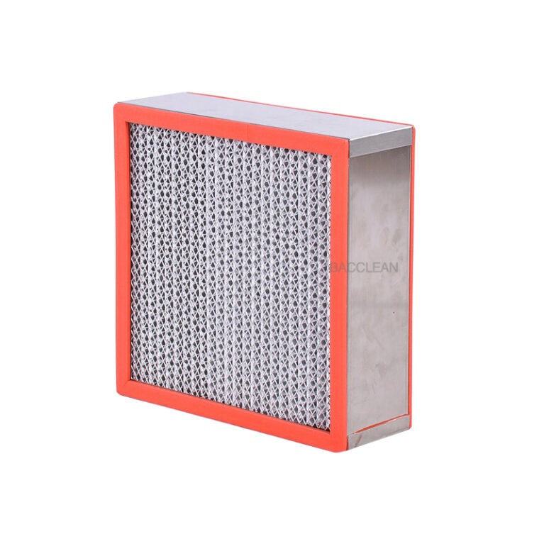
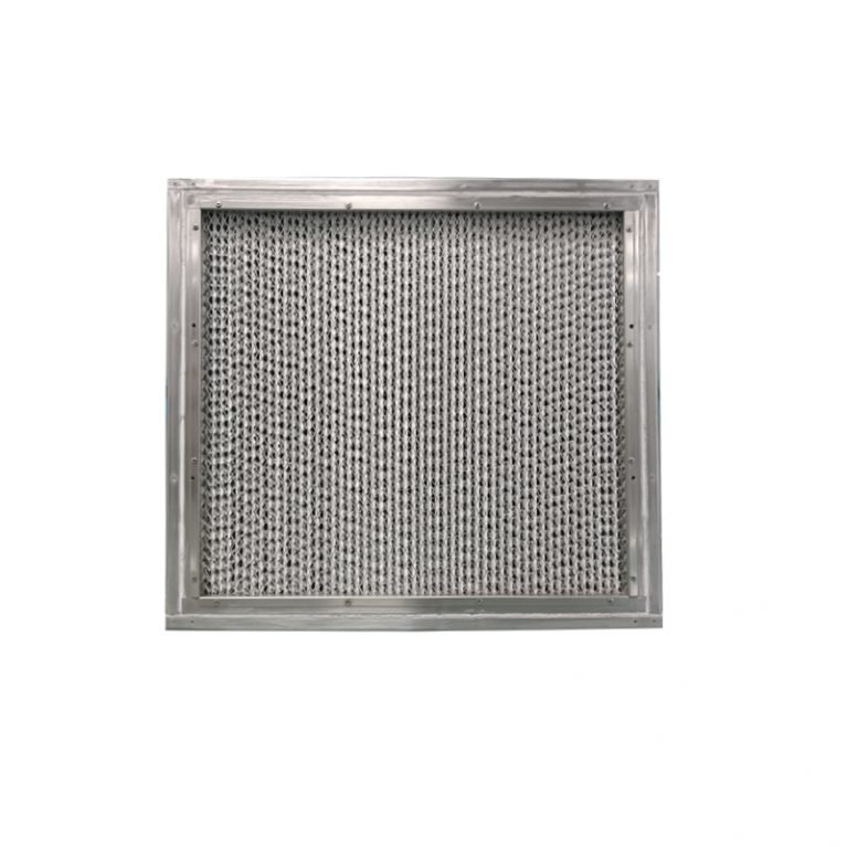
Principle The ceiling of the cleanroom is equipped with “high-efficiency air filters (HEPA)” or “ultra-high-efficiency air filters (ULPA)”. After passing through the filters, the air flows vertically downward at a uniform speed of 0.2 to 0.5m/s (similar to an “air waterfall”), pushing the particles towards the ground and then discharging them through the return air holes on the ground. Form a “unidirectional airflow channel from top to bottom”.
The uniformity of the airflow should be ≥90% (i.e., the difference in airflow velocity between different areas should be ≤10%), and “airflow vortices” (which may cause particle retention) should be avoided. The filter coverage rate should be ≥90% (100% full coverage for advanced processes), and the filters need to be regularly inspected (such as integrity tests) to prevent leakage.
2. Auxiliary areas (such as changing areas, temporary material storage areas)
The “non-unidirectional flow” is adopted, and the air is purified through wall-mounted HEPA filters or ceiling-mounted filters. The particle concentration is controlled at ISO Class 6 to Class 7, which can meet the requirements of personnel operation and material transition.
Iv. Pressure Control: Prevent external contamination from entering
The cleanroom should maintain positive pressure (relative to the external environment) to prevent unclean air from the outside from seeping in through gaps such as door gaps and pipe joints. Meanwhile, areas of different cleanliness levels need to maintain a “pressure gradient” to ensure that air flows from the high-cleanliness zone (such as Class 1) to the low-cleanliness zone (such as Class 5), preventing particles from the low-cleanliness zone from diffusing into the high-cleanliness zone.
1. Pressure difference requirements
Positive pressure between the cleanroom and the outdoor atmosphere: ≥15Pa (approximately 0.06 inches of water column);
Positive pressure between the high cleanliness area (such as the lithography area) and the adjacent low cleanliness area (such as the corridor) : ≥5 to 10Pa;
Special areas (such as the chemical waste liquid treatment room and the photoresist storage room) should maintain a negative pressure (≤-5Pa) to prevent the spread of harmful gases or volatile organic compounds (VOCs) into the production area.
2. Control mode
The exhaust air volume is controlled by “variable frequency regulation of the return air valve”, and in combination with the stable output of the intake air volume, the pressure is maintained stable. Pressure sensors should be installed in each area to monitor the pressure difference in real time. When an abnormality occurs, an automatic alarm will be triggered and adjustments made.
V. Chemical Pollutant Control: Trace-level Monitoring
In semiconductor processes, molecular-level chemical pollutants in the air (such as metal ions, volatile organic compounds (VOCs), and acidic/alkaline gases) can cause surface contamination of wafers and affect circuits
Personnel are the largest particle source (each person generates 1–10 million particles per minute). They must wear dust-free suits, masks, gloves, and shoes. Before entering the clean room, they pass through an air shower (high-pressure airflow to remove particles) and an air lock room (to balance pressure and block external air).
Production equipment (like photolithography and etching machines) must have a local clean unit to contain particles during operation. Seal equipment connections to the floor and walls to stop dust buildup.
Material control: Wafers, photoresists, and other materials need to enter the clean room through the “dust-free transfer window” (with ultraviolet disinfection and air flow purification), and the outer packaging needs to be removed and cleaned outside the clean room. The material transport trolley should be equipped with a brushless motor (to prevent carbon powder from falling off), and the wheels should be made of anti-static and dust-free materials.
Ii. Temperature and Humidity Control: Micron-level precision requirements
Semiconductor processes, like photolithography and thin film deposition, are very sensitive to temperature and humidity changes. Temperature fluctuations can cause wafer expansion or contraction, affecting alignment (e.g., a 1℃ change causes a 0.1μm deviation). Humidity changes can affect photoresist or metal film adhesion and cause static electricity buildup.
1. Temperature control
Control range: Generally, it is required to be 23℃±0.1℃ to ±0.5℃ (±0.1℃ for advanced processes, and ±0.5℃ for mature processes), and the temperature difference between different areas in the clean room (such as the photolithography area and etching area) should be ≤0.3℃.
Control mode: The “constant temperature and Humidity air conditioning System (MAU+AHU)” is adopted. The temperature is monitored in real time through precision sensors, and it is regulated in combination with variable frequency fans and electric heating/cold water coils to ensure uniform air flow temperature (avoiding local hotspots).
2. Humidity control
Control range: Generally, a relative humidity (RH) of 45%±5% is required (for some processes, such as aluminum metallization, RH≤30% is needed to prevent aluminum oxidation; for photolithography processes, RH stability is required to avoid moisture absorption of the photoresist).
Control method: Reduce humidity through a dehumidifier (rotary dehumidification or refrigeration dehumidification), or adjust humidity through steam humidification (using purified water to avoid impurities in the water from entering the air), ensuring that the humidity fluctuation is ≤2% per hour.
Iii. Airflow Organization: Unidirectional flow is dominant to avoid dead corners
The airflow design of a cleanroom must ensure that “particles are continuously discharged and do not remain or circulate above the wafers”. The core mode is vertical unidirectional flow (laminar flow), while some auxiliary areas adopt “horizontal unidirectional flow” or “non-unidirectional flow (turbulent flow)”.
Vertical unidirectional flow (core production area)
Principle The ceiling of the cleanroom is equipped with “high-efficiency air filters (HEPA)” or “ultra-high-efficiency air filters (ULPA)”. After passing through the filters, the air flows vertically downward at a uniform speed of 0.2 to 0.5m/s (similar to an “air waterfall”), pushing the particles towards the ground and then discharging them through the return air holes on the ground. Form a “unidirectional airflow channel from top to bottom”.
The uniformity of the airflow should be ≥90% (i.e., the difference in airflow velocity between different areas should be ≤10%), and “airflow vortices” (which may cause particle retention) should be avoided. The filter coverage rate should be ≥90% (100% full coverage for advanced processes), and the filters need to be regularly inspected (such as integrity tests) to prevent leakage.
2. Auxiliary areas (such as changing areas, temporary material storage areas)
The “non-unidirectional flow” is adopted, and the air is purified through wall-mounted HEPA filters or ceiling-mounted filters. The particle concentration is controlled at ISO Class 6 to Class 7, which can meet the requirements of personnel operation and material transition.
Iv. Pressure Control: Prevent external contamination from entering
The cleanroom should maintain positive pressure (relative to the external environment) to prevent unclean air from the outside from seeping in through gaps such as door gaps and pipe joints. Meanwhile, areas of different cleanliness levels need to maintain a “pressure gradient” to ensure that air flows from the high-cleanliness zone (such as Class 1) to the low-cleanliness zone (such as Class 5), preventing particles from the low-cleanliness zone from diffusing into the high-cleanliness zone.
1. Pressure difference requirements
Positive pressure between the cleanroom and the outdoor atmosphere: ≥15Pa (approximately 0.06 inches of water column);
Positive pressure between the high cleanliness area (such as the lithography area) and the adjacent low cleanliness area (such as the corridor) : ≥5 to 10Pa;
Special areas (such as the chemical waste liquid treatment room and the photoresist storage room) should maintain a negative pressure (≤-5Pa) to prevent the spread of harmful gases or volatile organic compounds (VOCs) into the production area.
2. Control mode
The exhaust air volume is controlled by “variable frequency regulation of the return air valve”, and in combination with the stable output of the intake air volume, the pressure is maintained stable. Pressure sensors should be installed in each area to monitor the pressure difference in real time. When an abnormality occurs, an automatic alarm will be triggered and adjustments made.
V. Chemical Pollutant Control: Trace-level Monitoring
In semiconductor processes, molecular-level chemical pollutants in the air (such as metal ions, volatile organic compounds (VOCs), and acidic/alkaline gases) can cause surface contamination of wafers and affect circuits