Before implementing the technical solution, it is necessary to first anchor the three core goals of airflow control, and all designs should revolve around these goals:
Directionality: Air flows along the preset path (such as vertically downward or horizontally forward), avoiding the formation of “vortices” above the wafer/equipment (vortices can retain particles and cause secondary pollution).
Uniformity: There is no significant fluctuation in the air flow velocity and direction within the clean area (such as a vertical flow velocity deviation of ≤10%), preventing the accumulation of particles in local areas.
High efficiency: The airflow can quickly carry away the particles generated in the clean area (such as those emitted by personnel and equipment) and discharge them through the return air system, avoiding the particles’ residence time exceeding the allowable range of the process (usually, the particles’ residence time in the clean area is required to be less than 1 second).
Ii. Core Step 1: Selection of Air Flow Organization Mode (Matching according to Cleanliness Requirements)
Different cleanliness areas (such as core production areas and auxiliary areas) have different requirements for air flow. It is necessary to first determine the corresponding air flow organization mode – this is the “top-level design” of air flow control and directly determines the subsequent equipment selection and layout. The mainstream semiconductor cleanroom models adopt the following three types, with “vertical unidirectional flow” as the core:
| Airflow organization pattern | Core principle | Applicable area | Requirements for key parameters |
| Vertical unidirectional flow (laminar flow) | Air flows vertically downward from the top of the clean room (filled with filters), covering the entire area like an “air waterfall”, and then is discharged through the ground return air holes, forming a “one-way channel from top to bottom”. | High cleanliness zones (ISO Class 1 to 5) : such as EUV lithography zones, wafer bonding zones, and etching zones |
Airflow velocity: 0.25-0.5m/s (for advanced processes, it needs to be ≥0.3m/s); Airflow uniformity: ≥90% (velocity difference between any two points ≤10%) Filter coverage rate: ≥90% (100% full coverage is required for Class 1 zone) |
| Horizontal unidirectional flow (laminar) | Air flows horizontally from one side of the clean room (such as a wall filter array) to the return air area on the other side, forming a “left-to-right/front-to-back unidirectional airflow” | Local high-cleanliness areas: such as wafer cleaning tables, photoresist coating areas (local process points need to be protected) |
Airflow velocity: 0.3-0.6m/s; Airflow coverage width: ≤3m (Excessive width will cause airflow attenuation and uneven speed) |
| Non-unidirectional flow (turbulence) |
Air is sent into the clean room through ceiling-mounted or wall-mounted filters without a fixed flow direction and is randomly discharged through the return air system. The concentration of particles is reduced by “air dilution” |
Low cleanliness auxiliary areas: such as changing areas, material temporary storage areas, cleanroom corridors (ISO Class 6~8) |
Air change rate: ≥20 to 60 times per hour (≥60 times for Class 6 and ≥20 times for Class 8). Avoid local dead corners (such as corners of walls, and reserve return air channels under equipment) |
After determining the air flow organization mode, a complete set of “supply air – filtration – return air” equipment system is required to implement the air flow control target. This system is the “hardware core” of airflow control and mainly includes five types of key equipment:
1. Air supply system: Provides a stable and clean air source
Air handling unit (AHU/MAU)
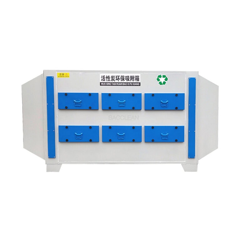
Function: First, it conducts “pre-treatment” on the outdoor fresh air (or indoor return air) – filtering large particles (primary filter), regulating temperature and humidity (heating/cooling coil, dehumidification/humidification module), and removing chemical pollutants (activated carbon adsorption, chemical filter), to ensure that the air sent into the clean room is “clean, constant temperature and constant humidity”.
Key requirements: Use variable frequency fans (which can dynamically adjust the wind speed according to the pressure and air volume requirements of the clean room to avoid energy waste); The fan must be a “brushless motor” (to prevent carbon powder from falling off and generating particles). The accuracy of temperature and humidity control needs to match the process requirements (such as ±0.1℃ temperature and ± 2%RH humidity).
Air supply duct and static pressure box
Function: Evenly convey the air processed by the AHU to the top of the clean room. The static pressure box can “buffer the airflow”, preventing the airflow from directly impacting the filter and causing uneven speed.
Material requirements: Smooth inner wall (to prevent particle adhesion), made of stainless steel or galvanized steel plate (corrosion-resistant and dust-free).
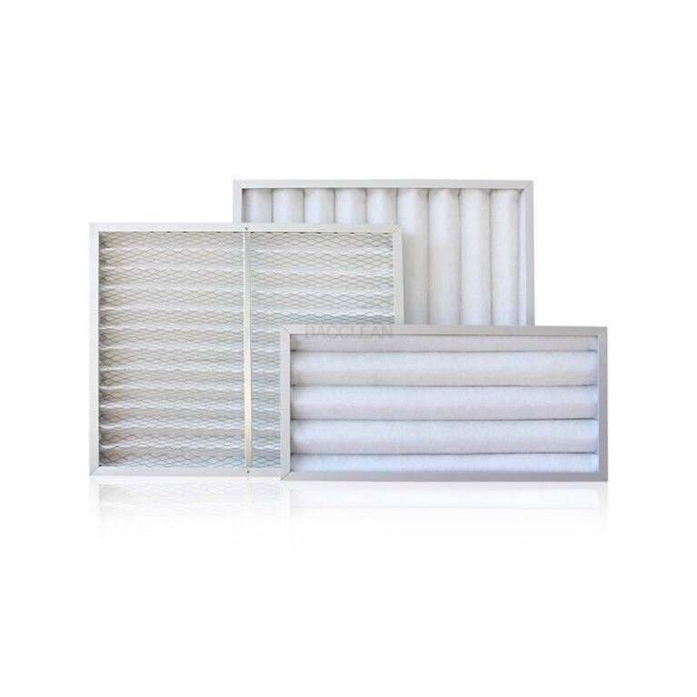
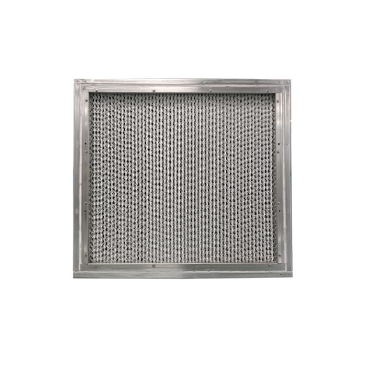
2. Filtration system: Intercepts particles to ensure clean airflow
Filtration is the “core barrier” for air flow control. It is necessary to gradually intercept particles of different sizes through “three-stage filtration” (primary efficiency → medium efficiency → high efficiency/ultra-high efficiency) to prevent the high-efficiency filter from clogging prematurely.
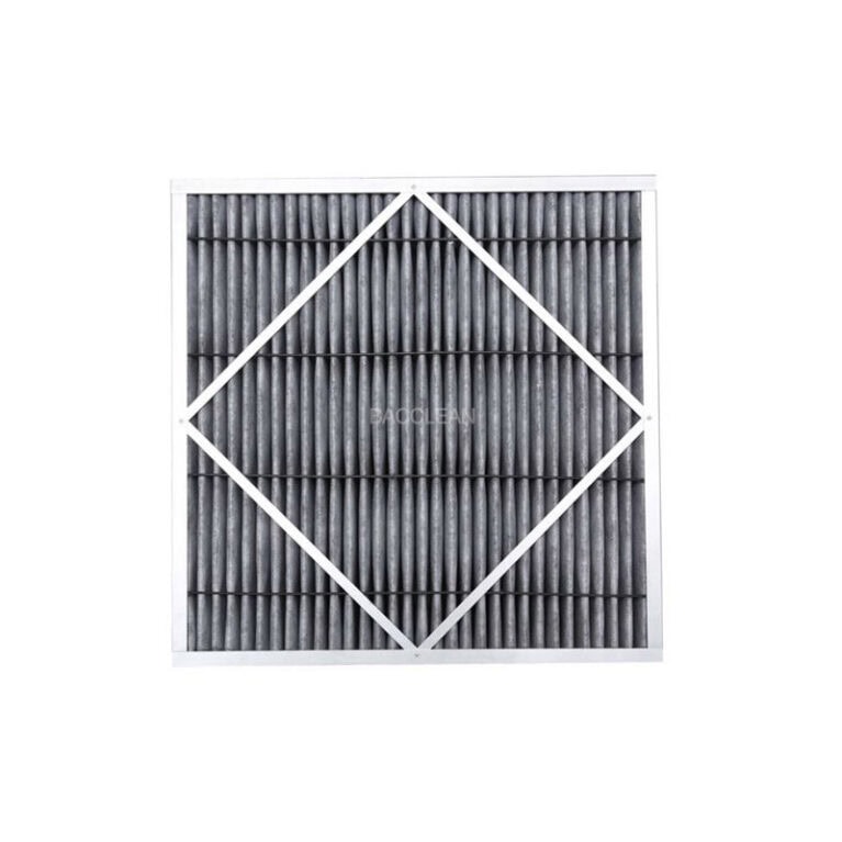
Primary filter (located at the AHU inlet) : Intercepts particles ≥5μm (such as dust and hair), protecting the subsequent medium-efficiency filter. The material is mostly non-woven fabric and needs to be replaced every 1 to 3 months.
Medium-efficiency filter (located inside the AHU) : Intercepts particles ≥1μm to protect the high-efficiency filter. The material is mostly glass fiber and needs to be replaced every 3 to 6 months.
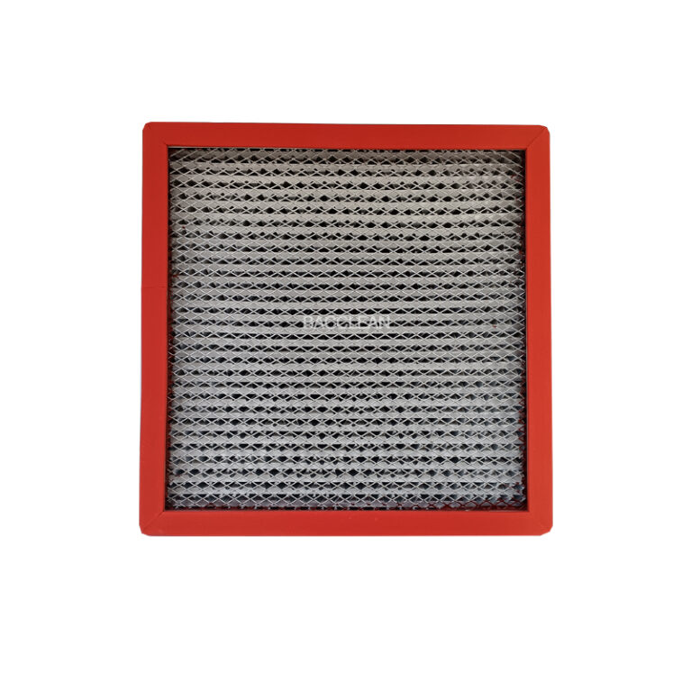
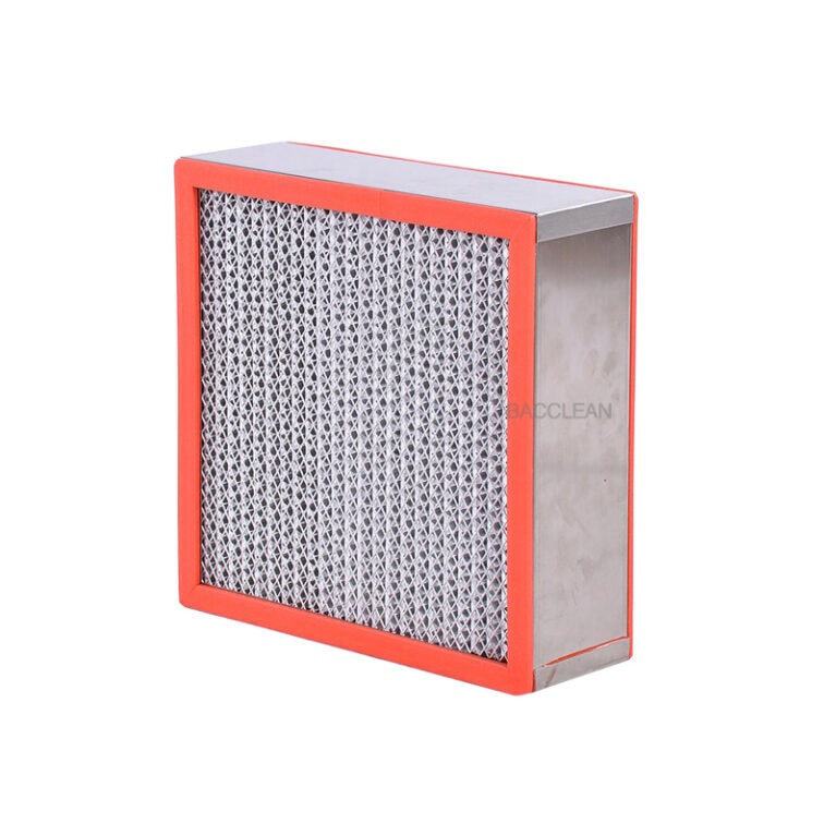
High-efficiency/ultra-high-efficiency filters (located at the top of the cleanroom, namely the “ceiling filter layer”) :
High-efficiency filter (HEPA) : Intercepts particles ≥0.3μm, with a filtration efficiency of ≥99.97%, suitable for ISO Class 5 to 8 zones.
Ultra-high Efficiency Filter (ULPA) : Intercepts particles ≥0.12μm, with a filtration efficiency of ≥99.999%, suitable for ISO Class 1 to 4 zones (such as 5nm process);
Installation requirements: The filter and the ceiling should be sealed with “sealant” or “liquid groove” (to prevent air from leaking through the gap and causing non-compliance with cleanliness standards), and an “integrity test” (such as DOP test) should be conducted every quarter to check for any damage.
3. Return air system: Ensure the directional discharge of air flow to form a circulation
The return air system is the key to the “closed loop” of airflow and needs to be coordinated with the supply air system to ensure that the airflow “only exits and does not return”, avoiding the retention of particles.
Return air path design.
Vertical unidirectional flow area: “Return air grilles” are laid on the ground (covering the entire ground or arranged along the periphery of the equipment). The airflow descends from the top, carrying particles through the grilles into the underground return air duct, and then returns to the AHU for reprocessing.
Horizontal unidirectional flow zone: The return air grille is located on the downstream side of the airflow (such as the bottom of the opposite wall), ensuring that the airflow completely covers the process area in the horizontal direction before being discharged.
Non-unidirectional flow area: The return air grille is mostly located at the corner of the wall or ceiling. It should be avoided to be directly facing the supply air outlet (to prevent short circuit of the airflow and avoid local dead corners).
Requirements for return air equipment
The return air duct should be equipped with a “medium-efficiency return air filter” (to intercept large particles raised from the ground and prevent contamination of the AHU).
The return air fan needs to be “linked with frequency conversion” for the supply air fan (ensuring that the supply air volume = return air volume + fresh air volume to maintain a stable positive pressure in the clean room).
4. Airflow rectification equipment: Optimize airflow uniformity and eliminate vortices
Even with a supply and return air system, local areas (such as under equipment or in corners) may still experience airflow vortices, which need to be optimized through rectification equipment.
Airflow diffusion plate (located below the filter) : It “disperses and homogenizes” the airflow sent out by the filter to prevent direct impact of the airflow on the wafer or equipment, forming a uniform vertical airflow.
Deflector plates (located around equipment) : When there is large equipment (such as photolithography machines) in the clean area, the equipment will block the airflow. Deflector plates need to be installed on the side of the equipment to guide the airflow around the equipment and prevent the formation of vortices beneath the equipment.
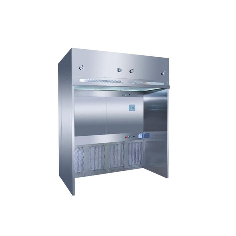
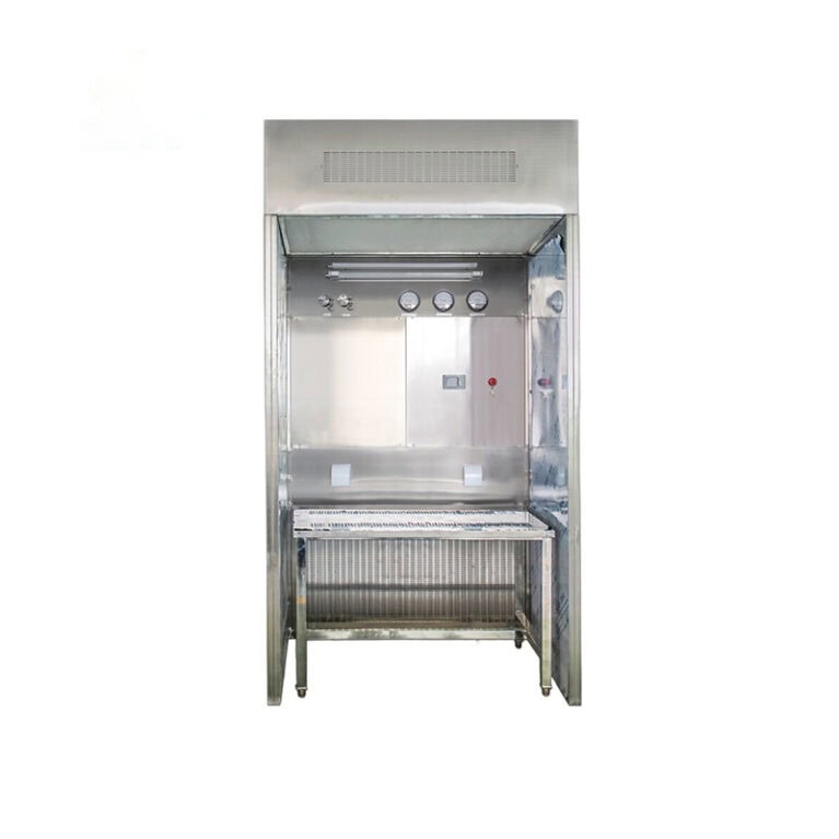
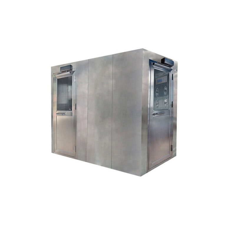
Air curtain machine (located at the entrance or transfer window of the clean room) : It forms a “horizontal air flow barrier” at the entrance to prevent the infiltration of low-cleanliness air from the outside, while not affecting the entry and exit of personnel/materials.
Iv. Core Link 3: Monitoring and Dynamic Regulation of Airflow Parameters (Software Assurance)
Air flow control is not a “one-time solution”. It requires real-time monitoring and dynamic adjustment to deal with air flow fluctuations caused by personnel movement, equipment operation, filter blockage, etc. This stage relies on the interaction of “sensors + control systems” :
1. Key parameter monitoring
Install the following sensors in different areas of the clean room (such as supply air outlets, above process equipment, and return air outlets) to collect data in real time:
Airflow velocity sensor: Monitors the velocity of vertical/horizontal airflow (accuracy ±0.02m/s) to ensure compliance with the design value (e.g., 0.3m/s±0.03m/s);
Airflow direction sensor: By means of “hot-wire anemometer” or “particle image velocimetry (PIV)” technology, it monitors whether there are vortices or reverse flows in the airflow (such as whether there is upward reverse flow of airflow beneath the equipment).
Particle counter: It monitors the concentration of particles ≥0.1μm and ≥0.5μm in the air in real time, and indirectly determines the efficiency of the airflow in carrying particles (if the particle concentration suddenly increases, it may be due to a decrease in airflow velocity or a damaged filter).
2. Dynamic regulation logic
The sensor data is transmitted in real time to the “Central Control System (BMS)”. The system automatically adjusts the equipment according to the preset threshold. The core regulation logic includes:
Air flow velocity regulation: If the air flow velocity in a certain area is lower than the set value (such as due to filter blockage), the BMS automatically increases the frequency of the supply air fan, increases the supply air volume, and restores the air flow velocity.
Pressure balance regulation: If the positive pressure between the cleanroom and the outside is insufficient (such as due to frequent door opening), the BMS automatically reduces the return air volume or increases the fresh air volume to maintain a stable positive pressure (preventing external air from seeping in).
Local airflow optimization: If vortices (increased particle concentration) occur around the equipment, the BMS can activate the “local clean unit” (such as a small HEPA fan) built into the equipment to supplement the directional airflow and eliminate the vortices.
V. Core Link 4: Auxiliary Design (Avoiding Airflow Interference)
In addition to the above-mentioned systems, the auxiliary designs, such as the layout, materials, and personnel operations within the cleanroom, will also directly affect the air flow control effect and need to be optimized simultaneously
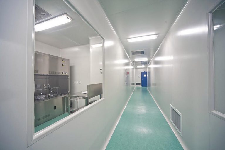
Equipment layout: Large and tall equipment (such as photolithography machines and etching machines) should be arranged along the direction of the airflow (vertical flow areas should be “reaching the sky and standing on the ground” to avoid blocking the airflow; horizontal flow areas should be parallel to the airflow direction). An “airflow channel” of ≥1.2m should be reserved between the equipment to prevent the airflow from being blocked.
Floor/Wall material: The floor should be made of “epoxy resin self-leveling floor” (smooth, seamless, avoiding particle accumulation; wear-resistant and anti-static), and the wall should be made of “stainless steel plate” or “color steel plate” (smooth inner wall, no dust generation, easy to clean), reducing the particles raised by air flow.
Personnel and material operations: Personnel should move along the “downstream direction of the airflow” (for example, in vertical flow areas, they should move from the edge of the clean area to the core process area to avoid disturbing the airflow and forming vortices). Material transport carts should be equipped with wheels that are “free of wheel marks and low in noise”, and their driving paths should avoid areas sensitive to air flow (such as above the photolithography area).
Summary: The essence of air flow control is “full-chain closed-loop management.”
The air flow control in a cleanroom is not the result of a single device, but rather a full-chain closed loop of “objective (directional, uniform, efficient) → pattern (unidirectional flow/non-unidirectional flow) → equipment (supply and return air + filtration) → monitoring (sensors) → regulation (BMS) → auxiliary design (layout/material)”. Taking the semiconductor ISO Class 1 zone (5nm process) as an example, its airflow control logic can be simplified as:
The AHU processes the fresh air into clean air with a temperature of “23℃±0.1℃ and RH45%±2%”.
Air is evenly distributed through the static pressure box to the top ULPA filter and flows vertically downward at a speed of 0.35m/s.
The airflow covers the surface of the wafer, carrying particles generated by personnel/equipment, and enters the return air duct through the ground return air grille.
The return air, after passing through the medium-efficiency filter, returns to the AHU, mixes with the fresh air, and is reprocessed to form a circulation.
The sensor monitors the air flow velocity and particle concentration in real time, and the BMS automatically adjusts the fan frequency to ensure parameter stability.
It is precisely through this collaborative solution of “hardware + software + management” that the strict requirements for airflow in advanced semiconductor manufacturing processes can be met, fundamentally avoiding chip defects caused by particulate contamination.