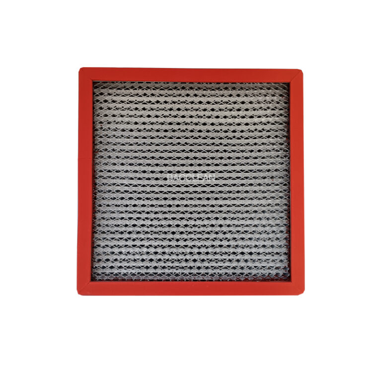
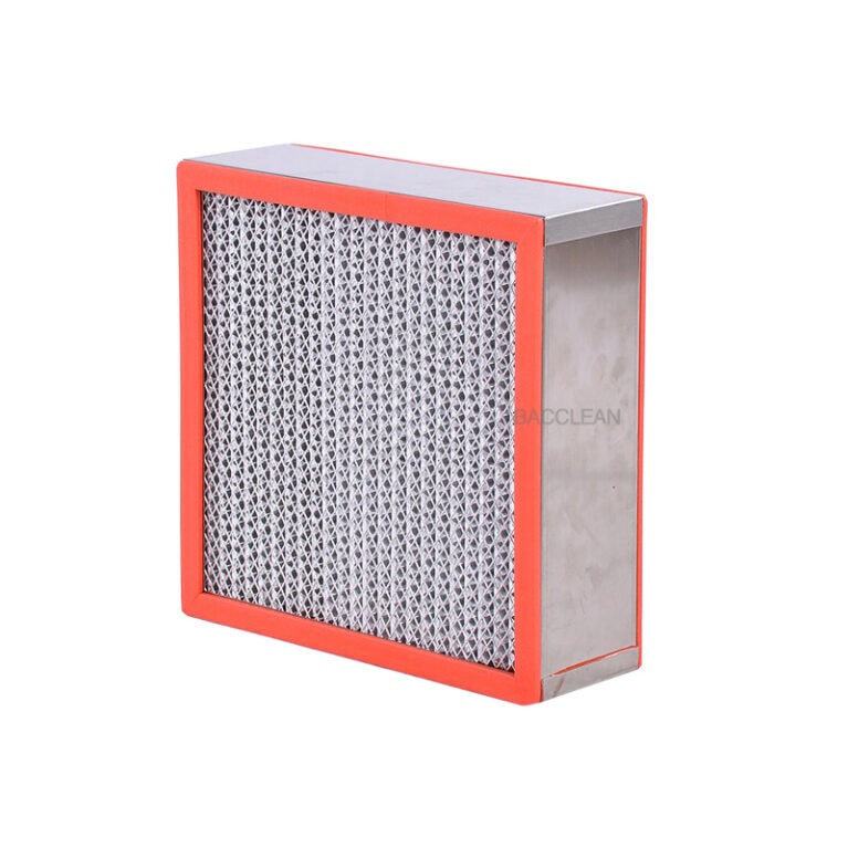
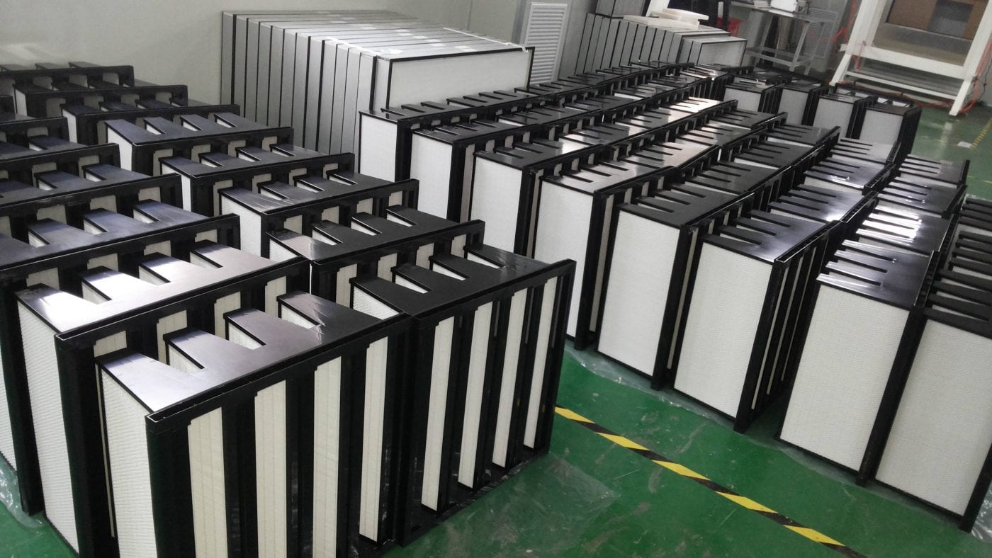
In the electronic manufacturing environment, ensuring the stable operation of V-shaped pleated high-efficiency filters (hereinafter referred to as “V-shaped high-efficiency filters”) is a core link in maintaining the cleanroom grade and guaranteeing production quality. A full life cycle management system needs to be established from five dimensions: selection and matching, installation control, operation monitoring, maintenance management, and environmental coordination. The specific measures are as follows:
I. Early Stage: Precise selection to match the clean requirements of electronic manufacturing from the source
Selection is the foundation for stable operation. It is necessary to precisely match parameters such as the cleanliness level (mainly ISO 3-5), air volume requirements, and pollutant characteristics of specific scenarios in electronic manufacturing (such as chip lithography rooms, PCB assembly workshops, packaging and testing rooms, etc.) to avoid unstable operation caused by “insufficient selection” or “excessive selection”.
The filtration efficiency matches the cleanliness grade
According to the cleanliness level requirements of the workshop, select the filter with the corresponding efficiency grade:
ISO Class 5 (Class 100) cleanroom: H13/H14 class (EN 1822 standard) is preferred, with an interception efficiency of 0.3μm particles ≥99.95%/99.995%.
ISO Grade 4 (Grade 10) and above: U15/U16 grade should be selected to meet the more stringent filtration requirements for fine particles (below 0.1μm).
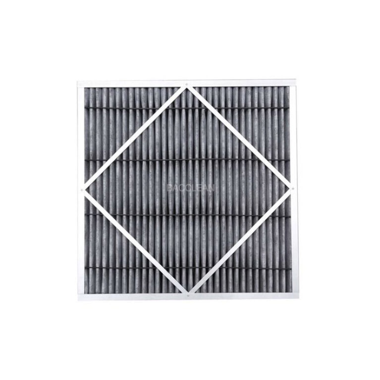
For core processes such as photolithography and ion implantation in chip manufacturing, additional attention should be paid to the adsorption capacity of the filter for “chemical pollutants (such as VOCs)” (activated carbon composite filter materials can be used in combination).
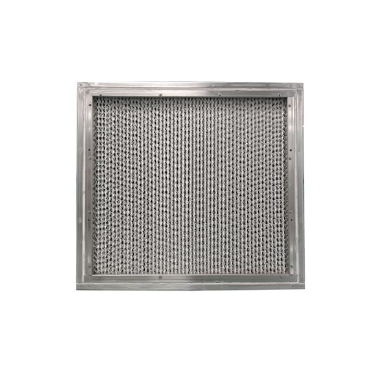
The air volume is compatible with the structure
According to the supply air volume requirements of the cleanroom (usually calculated by “air change rate”, for example, ISO level 5 requires 200-400 times per hour), select a V-type filter that matches the single rated air volume (common specifications: Avoid operating at an air volume exceeding 1000-3000 m³/h (which may cause a sudden increase in resistance and damage to the filter material) or at a low air volume (which may result in insufficient cleanliness).
For compact clean areas (such as clean chambers built into equipment), choose “thin V-shaped structure” or “multi-unit modular combination” to ensure uniform air distribution after installation.
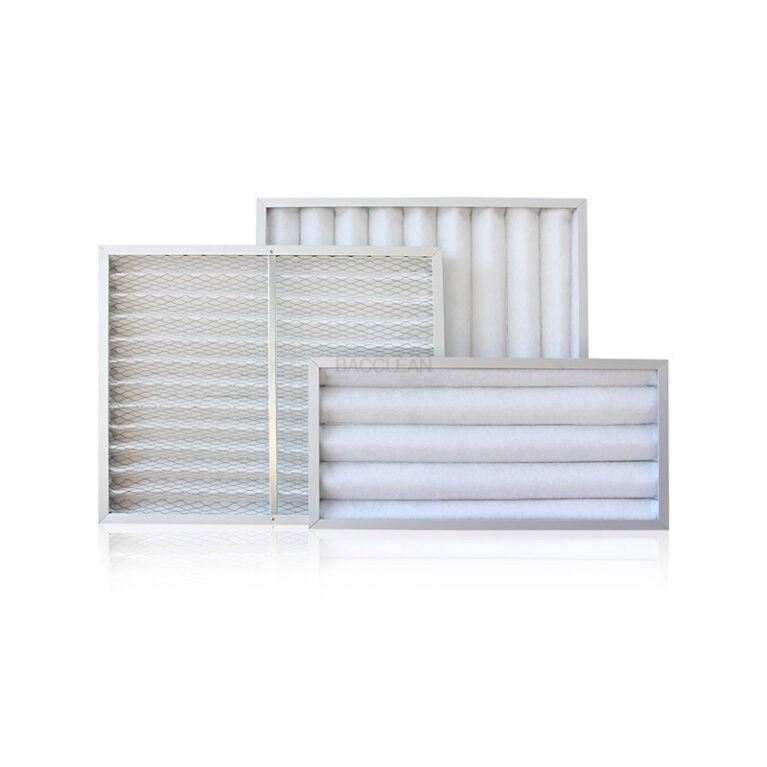
Selection of filter materials and frame materials
For filter materials, glass fiber filter paper (resistant to high temperatures and chemical corrosion, suitable for high-temperature process areas in electronic manufacturing) or PTFE-coated filter materials (low resistance, easy to clean dust, suitable for high-humidity areas) should be preferred. Ordinary non-woven fabric (prone to shedding fibers and contaminating components) should be avoided.
The frame is made of aluminum alloy or stainless steel (rust-proof and anti-deformation), and the sealant is “food-grade silicone sealant” (free from volatile pollution and meeting the “silicon-free requirements” of the electronics industry).
Second, mid-term: Strictly control installation and sealing to prevent “bypass leakage”
The “leakage risk” of V-type high-efficiency filters is a key hidden danger in electronic manufacturing (unfiltered air in the bypass can directly contaminate the clean area), and a standardized installation process must be adopted to ensure reliable sealing.
Pre-treatment before installation
Installation environment cleanliness: Ensure that the ceiling and air ducts of the clean room have been “purged and cleaned” (removing welding slag and dust inside the ducts) to prevent contaminants from adhering to the surface of the filter materials after installation.
Filter inspection: After opening the box, check whether the filter material is damaged or wrinkled, whether the frame is deformed, and whether the sealant is uniform. At the same time, verify the “Efficiency test report” (such as the MPPS efficiency certification in EN 1822).
Key steps for installation and sealing
Adopt “frame-pressing seal” or “liquid trough seal” :
General clean area: Use EPDM sealing rubber strips and press the frame tightly to ensure that the compression between the rubber strip and the installation frame reaches 30%-50% (avoid gaps).
Core clean area (such as photolithography room) : Liquid tank sealing must be adopted (insert the filter frame into the liquid tank filled with “special sealing liquid”) to achieve “gapless sealing” and eliminate bypass.
After installation, “uniform air distribution adjustment” : By adjusting the deflector plates inside the static pressure box, ensure that the air flow acts evenly on each pleat of the V-shaped filter material (to avoid excessive local air flow causing filter material wear).
Leakage detection after installation
“Scanning leak detection” must be carried out in accordance with ISO 14644-3 standard: Using an “aerosol photometer”, challenge aerosols (such as PAO oil mist) are injected upstream of the filter. The probe is used to scan along the “frame, sealing area, and filter material surface” of the filter. The leakage rate should be ≤0.01% (≤0.005% in the core area of electronic manufacturing). If leakage is found, immediate rework (replacing the sealing gasket or filter) is required.
Iii. In operation: Real-time monitoring of key parameters and timely warning of abnormalities
The operating status of the filter is dynamically tracked through the online monitoring system to avoid performance degradation or failure caused by “abnormal parameters”.
Core parameter monitoring
Differential pressure (resistance) monitoring: Install differential pressure sensors at the “upstream” and “downstream” of the filter to monitor in real time the changes from “initial resistance → operating resistance → final resistance” (typically the initial resistance is 150-200 Pa and the final resistance is 400-500 Pa). When the resistance approaches the final resistance, a “replacement warning” is triggered (to prevent fan overload and filter material damage caused by excessive resistance operation).
Cleanliness monitoring: Install “particle counters” at key workstations in the clean area (such as chip transfer tracks and PCB soldering points) to monitor the concentration of 0.3μm/0.5μm particles in real time. When the concentration exceeds the standard, prioritize checking whether the filter is leaking or its efficiency is declining.
Temperature and humidity monitoring: In electronic manufacturing, fluctuations in temperature (22±2℃) and humidity (45± 5%RH) can affect the resistance of filters (for instance, high humidity can cause the filter material to become damp and heavier, leading to an increase in resistance), and it is necessary to link the air conditioning system to stabilize the environmental parameters.
Air flow organization monitoring
The supply air velocity in the clean area (usually 0.3-0.5 m/s) is regularly detected by the “hot sphere anemometer” to ensure that the airflow flows parallel (laminar clean area), avoiding local uneven air velocity (forming vortex areas and accumulating contaminants) caused by the clogging of the pleat of the V-type filter.
Four. Later Stage: Scientific maintenance and replacement to extend service life and reduce risks
The maintenance of V-type high-efficiency filters needs to balance “operating life” and “cleanliness requirements”, avoiding excessive replacement (increasing costs) or delayed replacement (leading to failure of cleanliness).
Regular cleaning and pre-filtration protection
Upgrade of the pre-filtration system: Install “primary filter (G4) + medium filter (F8)” upstream of the V-shaped high-efficiency filter to intercept over 80% of large particles (such as dust and hair), reduce the dust-holding load of the V-shaped filter material, and extend its service life (usually by 30% to 50%).
Regular replacement of the pre-filter: The primary filter should be replaced every 1-2 months, and the medium-efficiency filter every 3-6 months to prevent the pre-filter from being clogged and causing the “air resistance to be transferred” to the V-type high-efficiency filter.
Replace according to the dual indicators of “resistance + time”
Prioritize replacement based on “final resistance” : When the pressure difference reaches the final resistance (such as 450 Pa), replacement is required even before the preset time.
Auxiliary replacement based on “usage time” : For the core process areas in electronic manufacturing, even if the resistance has not reached the final resistance, it is necessary to forcibly replace them every “1-2 years” (to avoid the aging of the filter material causing fiber shedding). The period for the ordinary area can be extended to 2 to 3 years.
“Clean Control” during the replacement process
When replacing, follow the “dust-free operation” : Operators must wear clean suits and dust-free gloves, and use “dust-free bags” to seal the old filter (to prevent dust from spreading during replacement). The new filter should be installed immediately after opening (exposure time should not exceed 10 minutes).
After replacement, re-check for leaks: After each replacement, a “aerosol scan leak test” must be conducted again to ensure that the new filter is installed and sealed properly.
V. Environmental Synergy: Control External Pollution sources of Clean rooms
The stable operation of V-type high-efficiency filters cannot do without “coordinated control of the external environment”, and it is necessary to reduce the load of pollutants entering the clean room from the source.
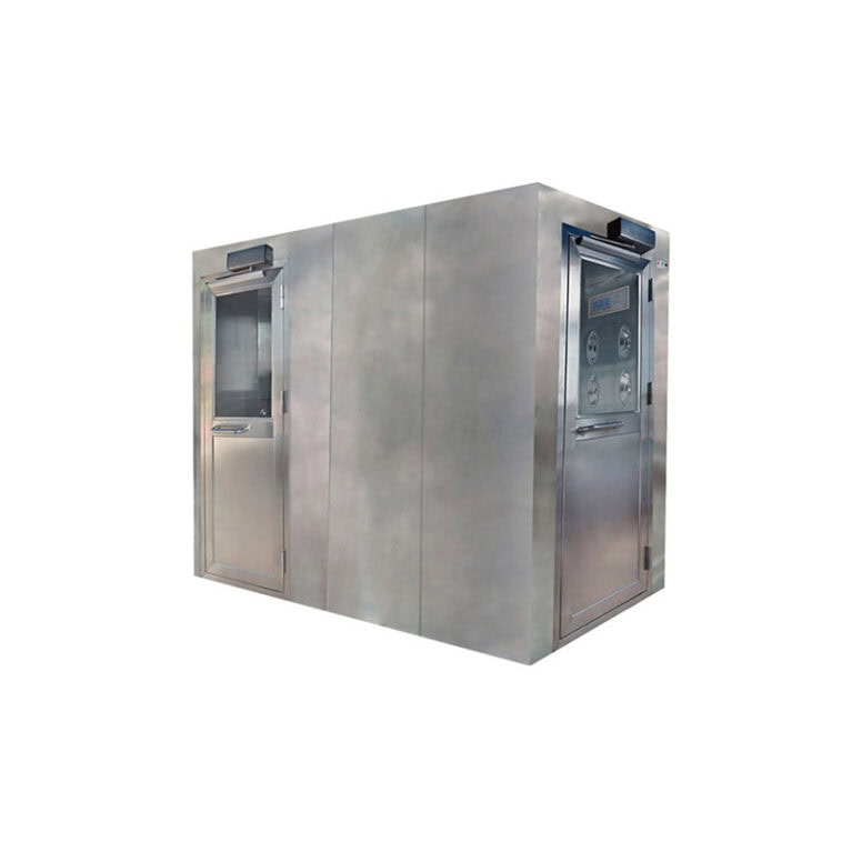
Personnel and material purification
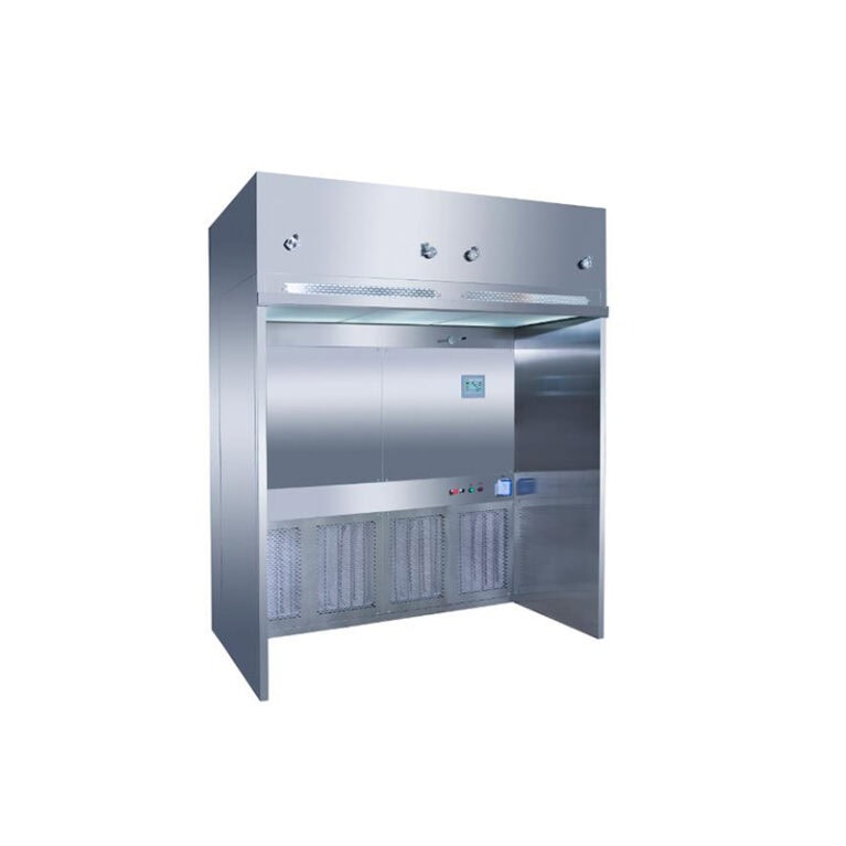
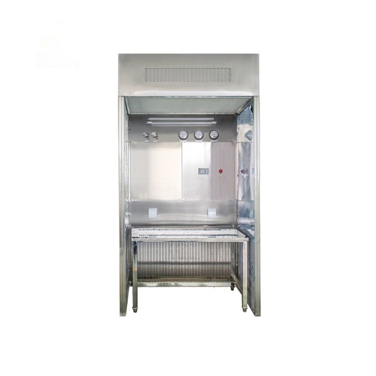
Personnel entry: It is necessary to go through “air shower room (to remove surface dust) + hand washing and disinfection + change into clean suits” to prevent personnel from bringing in dander or hair.
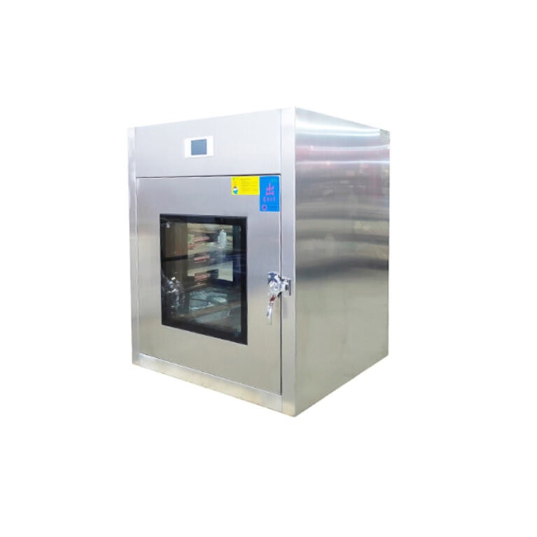
Material entry: Enter through the “transfer window (equipped with ultraviolet disinfection + high-efficiency filtration)”. The outer packaging needs to be removed outside the clean room to avoid dust contamination from the packaging materials.
Pollution control of equipment and processes
Production equipment: Regularly clean the metal debris and oil stains on the surface of the equipment (such as dust from PCB drilling machines). A “local exhaust + small V-type filter” can be installed near the equipment to directly intercept the pollutants generated by the equipment.
Process chemicals: Use “sealed storage tanks” to store photoresist, cleaning agents and other chemicals to prevent VOCs from adhering to the surface of the filter after volatilization (causing filter material blockage and efficiency reduction).
Vi. Emergency Response: Respond quickly to operational anomalies
When the V-type high-efficiency filter shows the following abnormalities, immediate measures should be taken to avoid affecting the electronic manufacturing production:
Sudden increase in pressure difference: Immediately check if the pre-filter is clogged. If the pre-filter is normal, it may be a “airflow short circuit” caused by local damage to the filter material. The machine needs to be shut down for leak detection and the filter replaced.
Excessive cleanliness: First, check if the particle counter is calibrated, then confirm through aerosol scanning whether the filter is leaking. If it is leaking, it needs to be replaced urgently, and trace the “last installation record” to find the cause.
Filter material damage: Immediately isolate the affected clean area, replace the filter, and then carry out “comprehensive cleaning + ultraviolet disinfection” on the clean area. Production can only resume after the cleanliness test is qualified.
Résumé
The stable operation of V-shaped pleated high-efficiency filters in electronic manufacturing essentially lies in “refined management throughout the entire life cycle” – from “selecting and matching clean requirements”, to “installation to prevent leakage”, then to “operation monitoring and early warning”, “maintenance and scientific replacement”, and finally combined with “environmental collaborative pollution control” to form a closed-loop management. Only when every link meets the strict standards of the electronics industry can the filter continue to function effectively, providing a reliable clean environment for the production of precision electronic components such as chips and PCBS.