The performance indicators of FFUs applied in the semiconductor field directly determine whether they can meet the strict requirements of chip manufacturing for ultra-cleanliness, high stability and low interference. These indicators can be classified into three major categories: core functional indicators (directly related to cleanliness control), operational stability indicators (ensuring long-term reliable operation), and environmental compatibility indicators (adapted to special scenarios in semiconductor factories), as detailed below:
I. Core Functional Indicators: Directly determine the level of cleanliness
Such indicators are the “core competitiveness” of FFU and directly affect the process yield of semiconductor wafers (such as chip defects caused by particle contamination).
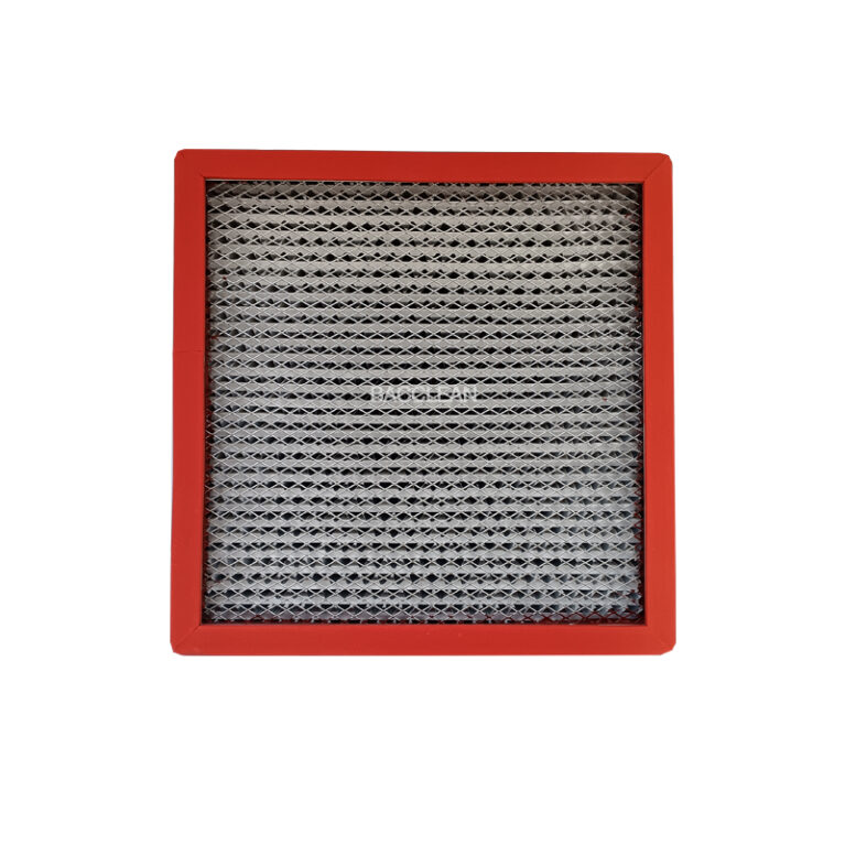
1. Filtration Efficiency
Definition: It measures the ability of a filter to remove particles from the air and is the core indicator for FFU to control cleanliness.
Requirements in the semiconductor field:
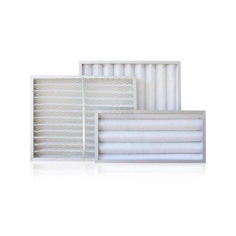
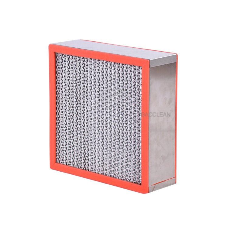
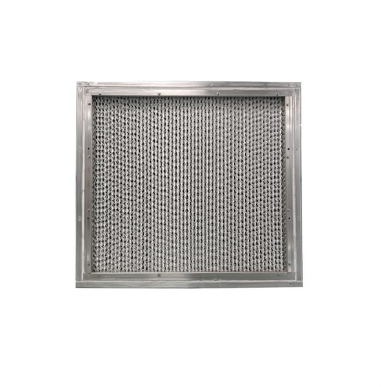
ULPA (Ultra-High Efficiency Air Filter) must be adopted instead of HEPA (High Efficiency Air Filter) commonly used in industrial scenarios.
The filtration efficiency for particles with a diameter of 0.1μm is ≥99.999% (ULPA Class 14 standard);
High-end processes (such as 3nm/2nm wafer manufacturing) need to reach **≥99.9995%** (ULPA Class 150 standard), or even higher, in order to remove “sub-micron” and “nanometer” particles (these particles are the main sources of pollution for advanced processes).
Key significance: The line width of semiconductor chips has entered the nanometer level (for instance, a 3nm line width is only equivalent to the diameters of a few atoms), and particles of 0.1μm are sufficient to cover multiple transistors, directly leading to chip failure.
2. Airflow Performance
It includes three dimensions: wind speed, air flow uniformity and air flow direction, which jointly determine whether clean air flow can effectively “isolate pollution”.
I. Core Functional Indicators: Directly determine the level of cleanliness
Such indicators are the “core competitiveness” of FFU and directly affect the process yield of semiconductor wafers (such as chip defects caused by particle contamination).
1. Filtration Efficiency
Definition: It measures the ability of a filter to remove particles from the air and is the core indicator for FFU to control cleanliness.
Requirements in the semiconductor field:
ULPA (Ultra-High Efficiency Air Filter) must be adopted instead of HEPA (High Efficiency Air Filter) commonly used in industrial scenarios.
The filtration efficiency for particles with a diameter of 0.1μm is ≥99.999% (ULPA Class 14 standard);
High-end processes (such as 3nm/2nm wafer manufacturing) need to reach **≥99.9995%** (ULPA Class 150 standard), or even higher, in order to remove “sub-micron” and “nanometer” particles (these particles are the main sources of pollution for advanced processes).
Key significance: The line width of semiconductor chips has entered the nanometer level (for instance, a 3nm line width is only equivalent to the diameters of a few atoms), and particles of 0.1μm are sufficient to cover multiple transistors, directly leading to chip failure.
2. Airflow Performance
It includes three dimensions: wind speed, air flow uniformity and air flow direction, which jointly determine whether clean air flow can effectively “isolate pollution”.
Outlet air velocity
The wind speed should be stable at 0.3 to 0.5m/s (a general standard in the semiconductor industry), and the fluctuation should be no more than ±0.1m/s (during long-term operation).
Meaning: If the wind speed is too low, an effective “clean air curtain” cannot be formed, and particles are prone to backflow. Excessively high wind speed can cause airflow disorder (generating vortices), which may instead draw surrounding contaminants into the clean area.
Airflow uniformity
The wind speed deviation at the FFU outlet section should be no more than 15% to ensure that the airflow is “vertical and uniform” downward (forming a “laminar clean area”).
Meaning: Avoid local airflow dead corners and prevent particles from depositing on the wafer surface.
Airflow direction
Requirements: Strictly vertical downward (within ±2° deviation), horizontal or inclined airflow is not allowed.
Meaning: In conjunction with the exhaust system of semiconductor equipment, it forms an airflow circulation of “upward supply and downward exhaust”, forcibly removing contaminants around the equipment and wafers.
3. Cleanliness Class (Cleanliness class)
Definition: The air cleanliness of the area covered by FFU is usually measured by the standard of “the number of particles ≥0.1μm per cubic foot of air”.
Requirements in the semiconductor field:
Front-end wafer manufacturing (core processes such as photolithography and etching) : It is necessary to support clean areas of Class 1 to Class 10 (i.e., ≤1 to 10 0.1μm particles per cubic foot).
Back-end packaging and testing: It needs to support clean areas ranging from Class 100 to Class 1000.
Key significance: The cleanliness level directly corresponds to the process yield – for instance, in the manufacturing of 12-inch wafers, the defect rate in a Class 1 environment can be reduced by over 90% compared to a Class 100 environment.
Ii. Operational stability indicators: Ensure long-term continuous production
Semiconductor factories need to operate continuously for 24 hours (a one-hour shutdown could cause losses of millions of dollars), so the “reliability” and “stability” of FFUs are of vital importance.
1. Fan performance and reliability
Wind pressure regulation capability: The fan must have a stable static pressure regulation function, which can automatically compensate for the wind speed according to the changes in the resistance of the filter (such as the resistance increases after the filter accumulates dust) to ensure stable air output (avoiding a decrease in wind speed due to increased resistance).
Continuous operating life: The MTBF (Mean Time Between Failures) of the fan should be ≥50,000 hours (approximately 5.7 years), and it should support 24-hour continuous operation.
Motor type: Brushless DC motors (BLDC) are preferred over brushed motors – BLDC motors have no carbon brush wear, which can reduce “wear particle pollution”, and have a longer lifespan and lower energy consumption.
2. Monitoring and linkage capabilities
Real-time monitoring function: Built-in sensors are required to monitor parameters such as wind speed, filter pressure difference (for determining lifespan), temperature and humidity in real time, and output data through the display screen or communication interface.
Intelligent linkage: Supports linkage with factory MES (Manufacturing Execution System) and cleanroom central control system to achieve:
Filter life warning (automatically reminds for replacement when the pressure difference exceeds the threshold);
Automatic fault alarm (such as fan stopping, abnormal wind speed);
Multiple FFUs work in coordination for regulation (to avoid local airflow conflicts).
Significance: Reduce manual intervention and prevent the loss of control over cleanliness caused by the failure to detect FFU faults in time.
3. Energy Consumption Index
Under the premise of meeting the wind speed and filtration efficiency requirements, the power consumption of a single unit should be ≤100 to 150W (depending on the size of the FFU, such as 1200×600mm specification).
Significance: Semiconductor factories typically deploy thousands of FFUs. Low energy consumption can significantly reduce the overall operating costs of cleanrooms (energy consumption accounts for more than 30% of the total operating costs of cleanrooms).
Iii. Environmental Compatibility Indicators: Adapted to the special scenarios of semiconductor factories
Semiconductor factories have special environments such as chemical corrosion, vibration sensitivity, and electromagnetic interference. Ffus need to have corresponding “anti-interference capabilities”.
1. Chemical Resistance
The FFU’s casing (typically made of stainless steel or aluminum alloy), filter frame, sealant and other components must be resistant to corrosive gases (such as fluorine, chlorine, ammonia, silane, etc.) and cleaning agents (such as isopropyl alcohol) commonly used in semiconductor processes.
Meaning: To prevent the generation of “shedding particles” (secondary pollution) after component corrosion, or the infiltration of unfiltered air into the clean area due to seal failure.
2. Low Vibration
The vibration amplitude during operation should be ≤0.5μm (within the frequency range of 10 to 1000Hz), which is much lower than that of ordinary industrial FFUs (usually ≤2μm).
Semiconductor core equipment (such as ASML lithography machines) is extremely sensitive to vibration – an amplitude exceeding 0.1μm may cause the lithography pattern to shift (due to the precision requirement of nanoscale line width). The low vibration of FFU can prevent interference with peripheral equipment.
3. Low Noise
Requirement: Operating noise ≤55dB(A) (measured at A distance of 1 meter), and in some high-end scenarios, ≤50dB (A).
Meaning: The clean area of a semiconductor factory is usually a confined space. Excessive noise can affect the comfort of operators and may even cause fatigue damage to the precision components of the equipment in the long term.
4. Electrostatic Control (ESD Control
The housing and filter frame of the FFU should have anti-static performance (surface resistance 10⁶ to 10¹¹Ω), and in some scenarios, an “ion air bar” should be integrated to actively eliminate static electricity in the airflow.
Meaning: Semiconductor wafers and chips are prone to static electricity, which can attract particles in the air (causing “electrostatic pollution”) and even break down the nanoscale circuits of the chips (electrostatic discharge damage).
Iv. Other Key Indicators: Details determine reliability
1. Filter lifespan and replacement convenience
The service life of the filter is usually ≥12 to 18 months (depending on the pollution concentration of the usage environment).
A “quick replacement structure” (such as a drawer-type filter) needs to be designed to prevent unfiltered air from entering the clean area during the replacement process (i.e., “zero leakage replacement”).
2. Leakage Rate
The leakage rate of the entire FFU (including the sealing area between the filter and the frame, and the joint area of the casing) should be ≤0.01% (tested in accordance with ISO 14644-3 standard).
Meaning: To prevent unfiltered contaminated air from seeping in through gaps and damaging the cleanliness of the clean area.
Summary: The core logic of performance indicators for semiconductor FFUs
The performance requirements for FFUs in the semiconductor field are essentially “to control parameters to the extreme and avoid any risks that may affect the yield of chips” – from “filtration efficiency” to “airflow stability”, and then to “low vibration and corrosion resistance” Each indicator directly corresponds to the pain points in semiconductor manufacturing (such as particle contamination, equipment interference, and process compatibility). As the manufacturing process advances towards 1nm and below, the performance indicators of FFUs will be further upgraded (such as nano-particle filtration and AI adaptive wind speed regulation), becoming the “invisible cornerstone” supporting advanced semiconductor manufacturing.