Daily Maintenance Guide for Laminar Flow Transfer Windows: Ensuring a Clean Environment and Stable Operation of Equipment
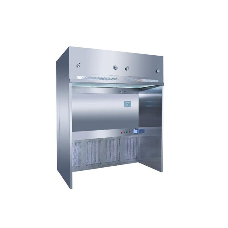
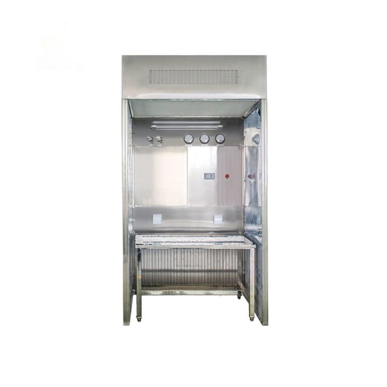
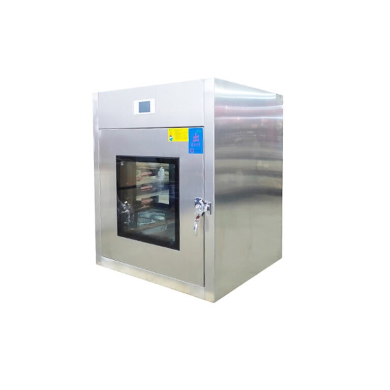
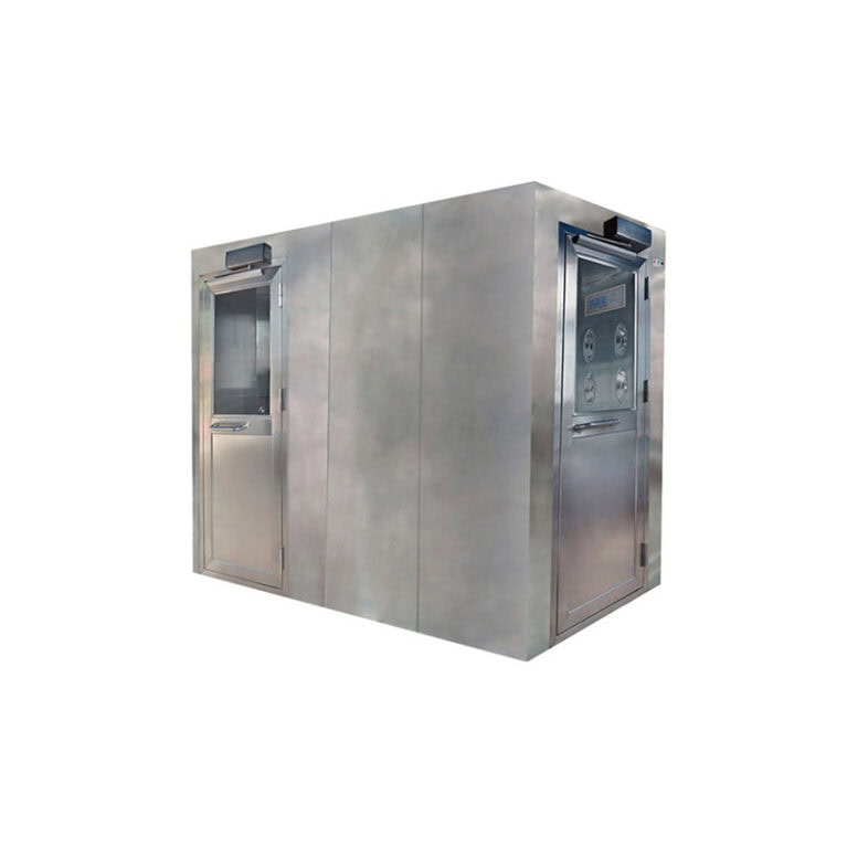
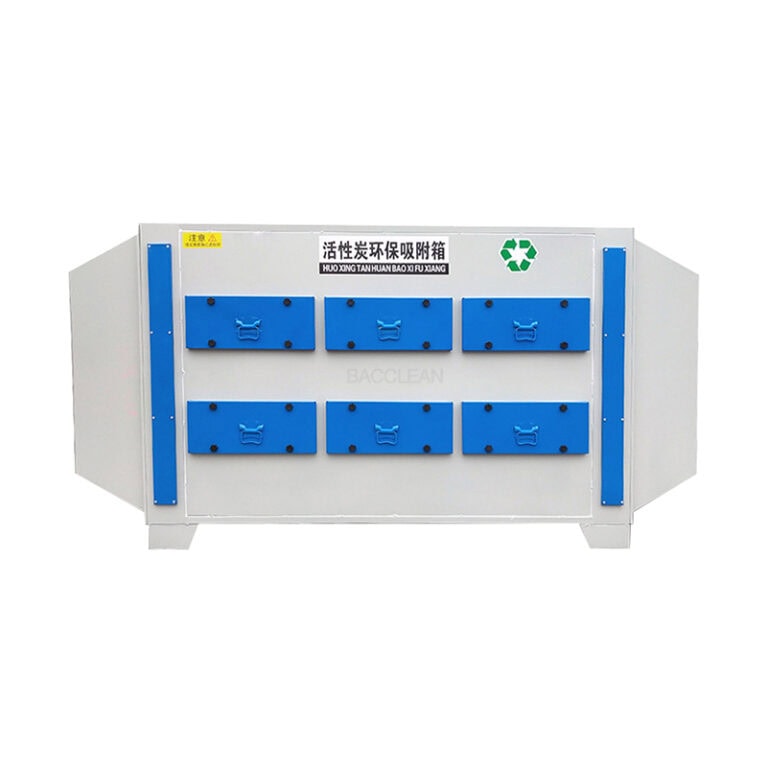
Laminar flow transfer Windows, as the core “isolation transfer equipment” between cleanrooms and non-clean areas as well as regions of different cleanliness levels, their sealing performance, filtration efficiency and air flow organization directly affect the overall cleanliness of the cleanroom. Proper daily maintenance not only extends the service life of equipment but also avoids the risk of cross-contamination. It is suitable for scenarios with strict cleanliness requirements such as pharmaceutical, electronic, food, and biological laboratories. The following are detailed key points for daily maintenance:
I. Daily Inspection: Basic status Confirmation (Every 10 minutes, at least once per shift)
Appearance and seal inspection
Check whether the transfer window box and door body are deformed, scratched or damaged, and whether the glass window is clean without stains or cracks to ensure a clear view.
Verify the double-door interlock function: After closing one side door, try to open the other side door to confirm that they cannot be opened simultaneously (when the interlock fails, it should be immediately deactivated to avoid pressure difference imbalance in the clean area).
Check the door sealing strip: Touch the sealing strip with your hand to see if it is intact, without aging, cracking or falling off. After the door is closed, it should fit tightly against the box without obvious gaps (you can test it with a piece of paper: once inserted into the door gap, it cannot be easily pulled out).
Operation status detection
After turning on the equipment, observe whether the fan operates smoothly without any abnormal noise (such as unusual sounds or vibrations), and whether the control panel indicator lights display normally (power, operation, and interlock status lights).
Check the air flow velocity: Use an anemometer to uniformly select 3 to 5 measurement points (such as the center and four corners) inside the transfer window to measure the average wind speed. It should comply with the rated standard of the equipment (usually 0.3 to 0.5m/s, subject to the manufacturer’s parameters). A wind speed that is too low may result in non-compliance with the cleanliness standard.
Confirm the lighting and ultraviolet disinfection functions (if configured) : The brightness of the lighting fixtures is normal, the ultraviolet lamps can start normally, and there is no flicker or odor during operation.
Cleaning and disinfection
Use a clean cloth dipped in 75% medical alcohol or a disinfectant that meets the requirements of the clean area (such as quaternary ammonium salts) to wipe the internal cavity, door body, handle and glass window of the transfer window. Pay special attention to cleaning the dust and stains in the corners and crevices to avoid the accumulation of dust and the breeding of bacteria.
After disinfection, turn on the fan and run it for 5 to 10 minutes to expel the residual disinfectant odor and ensure that the transferred items are not contaminated.
Ii. Regular Maintenance: Deep maintenance of core components (carried out according to the frequency/time of operation)
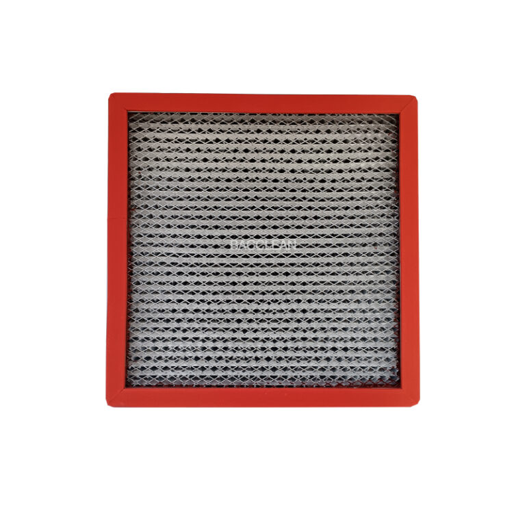
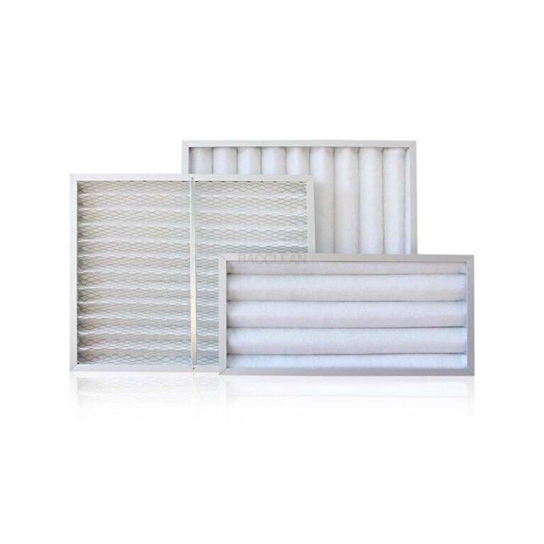
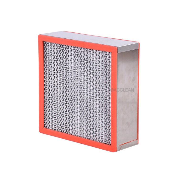
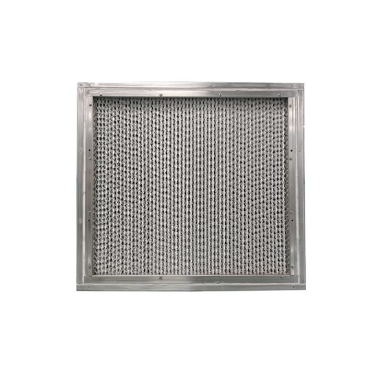
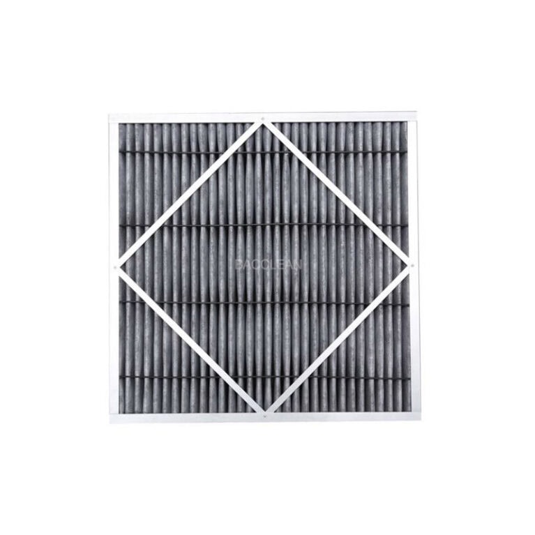
1. Maintenance of High-Efficiency Filters (HEPA) (Core Key)
Inspection cycle: For the primary filter, once every 1-3 months; for the high-efficiency filter, once every 6-12 months (or as indicated by the differential pressure gauge).
Maintenance content
Check the reading of the differential pressure gauge: The initial differential pressure of the high-efficiency filter is usually 100-200Pa. When the differential pressure exceeds twice the initial value (or reaches 400Pa), it needs to be replaced in time; otherwise, it will lead to insufficient air volume and a decrease in filtration efficiency.
When replacing the filter: It should be operated in a clean environment. Open the inspection door of the transfer window, remove the old filter, and be careful to avoid dust on the surface of the filter falling into the clean area. The new filter should be inspected to ensure that its appearance is undamaged and the sealant is intact. During installation, make sure it fits closely with the installation frame without any air leakage gaps.
The primary filter can be cleaned according to the contamination situation (such as rinsing with clean water or blowing back with compressed air). After cleaning, it should be dried before installation. If the filter material is damaged, it needs to be replaced directly.
2. Maintenance of fans and motors
Maintenance cycle: 3 to 6 months per maintenance.
Maintenance content
Check whether the fan impeller is covered with dust. Use compressed air (pressure ≤0.4MPa) to blow the dust off the impeller from the inside out to prevent dust accumulation from causing increased vibration, noise or reduced air volume of the fan.
Check the operating temperature of the motor: After running for 30 minutes, touch the motor housing with your hand. The temperature should be ≤60℃. If it overheats, check whether it is due to fan blockage, bearing wear or abnormal voltage.
Motor bearing lubrication: Add special lubricating oil (such as lithium-based grease) once every 6 to 12 months to prevent dry wear of the bearings and extend the service life of the motor.
3. Electrical system maintenance
Maintenance cycle: Once every 6 months.
Maintenance content
After turning off the power, check whether the internal circuit connections of the control panel are firm, without any loosening or oxidation, and whether the terminal blocks are fastened tightly.
Test the sensitivity of the interlock switch: Repeatedly open and close the door body to confirm that the interlock function is reliable. If there is a false trigger or failure, the switch position needs to be adjusted or the parts replaced.
Check the service life of the ultraviolet lamp: The rated service life of the ultraviolet lamp is usually 8,000 hours. After exceeding the service life, it should be replaced in time to avoid the decline of disinfection effect (the usage time record can be set on the control panel).
4. Sealing and Structural Maintenance
Maintenance cycle: Once every 6 months.
Maintenance content
Replace aged sealing strips: If the sealing strips harden, crack or lose elasticity, they should be replaced as a whole to ensure the sealing performance of the door body.
Inspect the box structure: Check whether the box frame is corroded or deformed, and whether the screws are loose. Tighten or repair them in time to avoid affecting the sealing performance and stability of the equipment.
Iii. Specialized Maintenance: Special Scenarios and Fault Handling
1. Special environment maintenance (such as high humidity, high dust, and corrosive environments)
Shorten the cleaning cycle: Add one internal cleaning per day and perform surface dust removal on the filter and fan once a week.
Strengthen sealing protection: Apply a small amount of silicone grease on the surface of the sealing strip to enhance sealing performance and anti-aging ability. Regularly check the box body for any corrosion marks and carry out anti-corrosion treatment in a timely manner.
Frequently replace the filters: once a month for the primary filter and once every 3 to 6 months for the high-efficiency filter. Adjust according to the actual pollution situation.
2. Common Fault Handling
Possible causes and handling methods of the fault phenomenon
If the interlock switch for both doors can be opened simultaneously is damaged or the wiring is loose, check the interlock switch, adjust its position or replace it. Tighten the terminal blocks
Insufficient air volume, low air velocity, clogged filter, dust accumulation on the fan, abnormal motor speed. Clean/replace the filter. Blow clean the fan impeller; Check the motor voltage and bearings
Abnormal noise from the fan, uneven dust accumulation on the impeller due to vibration, bearing wear, loose installation, and dust on the balance impeller. Replace the bearing; Tighten the screws that fix the fan
If the ultraviolet lamp does not light up, the lamp tube is damaged, the ballast is faulty, or the switch has poor contact, replace the ultraviolet lamp. Check the ballast; Repair the switch contact points
The control panel shows no response. There is a power failure, a blown fuse, or an open circuit. Check the power socket. Replace the fuse; Check for line breakpoints
Iv. Maintenance Precautions
All maintenance operations must be carried out after the equipment has been shut down and the power supply has been cut off to avoid electric shock or mechanical injury. When it comes to filter replacement and electrical maintenance, it must be carried out by professional technicians.
During the maintenance process, records should be kept well, including cleaning time, filter replacement date, differential pressure data, fault handling situation, etc. A maintenance file for the equipment should be established to facilitate traceability and subsequent optimization.
When the transfer window is not in use for a long time (more than one month), the power supply should be turned off, the internal cavity should be cleaned and disinfected, the door body should be sealed, and the fan should be started and run for 30 minutes regularly (monthly) to prevent the equipment from getting damp and the components from aging.
The selection of disinfectants should match the requirements of the clean room. Avoid using disinfectants with strong corrosiveness and easy residue to prevent damage to the surface of the equipment and the filter materials of the filters.
By standardizing the implementation of the above daily inspections and regular maintenance, it can be ensured that the laminar flow transfer window is always in the best operating condition, effectively isolating the contamination transfer between the clean area and the non-clean area, and providing a reliable guarantee for the cleanliness of the production and experimental processes. In case of complex faults (such as fan burnout or severe deformation of the box), it is recommended to contact the equipment manufacturer in a timely manner for professional maintenance.
How to replace the filter of the laminar flow transfer window?
Laminar Flow Transfer Window Filter Replacement Guide: Step-by-step Operation + Key Precautions
The filters of laminar flow transfer Windows (primary filters + high-efficiency HEPA filters) are the core components for ensuring the cleanliness of the airflow. The standardization of replacement operations directly affects the filtration efficiency and the risk of contamination in the clean room. The following is a standardized replacement process suitable for clean scenarios such as pharmaceuticals, electronics, and laboratories, including tool preparation, step-by-step operation, and key points to avoid pitfalls. Even beginners can quickly get started
I. Preparations before Replacement: Environment, Tools and consumables
Environmental requirements
Replacement should be carried out on the clean area side (such as in a 10,000-level / 100,000-level clean room) to prevent dust from non-clean areas from entering the equipment or the clean area.
Turn on the air conditioning system of the clean room and the transfer window fan 30 minutes in advance to purify the surrounding air. If conditions permit, clean cloths can be laid around the transfer window to prevent dust from scattering during operation.
2. Essential tools and consumables
Tools: Screwdriver (cross-head/flat-head), wrench, gloves (clean latex gloves), mask (dust-free mask), goggles, compressed air spray gun (pressure ≤0.4MPa), cloth, 75% medical alcohol.
Consumables: New filters of compatible models (primary/high efficiency, please confirm that the size and sealing method are consistent with the original equipment), sealant (if the high efficiency filter is not pre-sealed), garbage bags (clean grade).
3. Safety premise
Turn off the main power supply of the transfer window, unplug the plug or turn off the air switch to prevent the equipment from being mistakenly started during the replacement process.
Record the initial pressure difference of the high-efficiency filter (read the value of the pressure difference gauge before replacement to facilitate the subsequent comparison of the operating status of the new filter).
Ii. Step-by-step replacement process: Primary filter + high-efficiency filter
(1) Replacement of primary filters (washable type/Disposable type)
Disassemble the old filter
Locate the inspection door of the primary filter on the side or back of the transfer window (usually snap-on or screw-fixed), unscrew the fixing screws with a screwdriver, and open the inspection door.
The primary filter is generally drawer-type or fixed with clamps. Gently pull out the old filter, and be careful not to let the dust on the filter material fall off (you can first gently blow off the surface dust with compressed air, and then put it into a clean garbage bag and seal it).
2. Clean the installation frame
Use a clean cloth dipped in 75% alcohol to wipe the inner side and slots of the installation frame of the primary filter to remove accumulated dust and stains, ensuring that the installation surface is flat and free of debris (to avoid affecting the sealing effect).
If the frame is rusted or deformed, simple repairs should be made first (such as grinding the rusted areas). In severe cases, contact the manufacturer to replace the frame.
3. Install a new filter
Check the new primary filter: the appearance should be undamaged, the filter material should not fall off, and the frame should be intact. Confirm that the model matches the installation dimensions.
Push the filter into the slot in the original direction to ensure that the filter frame is closely attached to the installation frame without any looseness or gaps (you can gently press around the filter to confirm that it is firmly fixed).
Close the inspection door, tighten the screws or fasten the clips to ensure that the inspection door is well sealed.
(II) Replacement of High-Efficiency Filters (HEPA) (Core Key Steps)
Disassemble the old high-efficiency filter
Open the high-efficiency filter inspection panel at the top or back of the transfer window (usually fixed with multiple screws), slowly remove the panel and place it on a clean cloth.
High-efficiency filters are usually fixed on the mounting base by means of pressure strips, clips or bolts. Loosen the fixing parts with a tool and gently remove the old filter (do not lift the filter material vertically to avoid the filter material breaking and causing dust to spread).
Immediately put the old filter into a clean garbage bag, seal the bag opening, and take it out of the clean area for disposal in accordance with hazardous waste standards (do not discard it at will, especially in the medical and biological scenarios where environmental protection requirements must be met).
2. Cleaning and inspection of the installation base
Clean the accumulated dust on the surface of the mounting base with a compressed air spray gun (blowing from the inside out), and then wipe the sealing surface of the mounting base (the part where the high-efficiency filter contacts the mounting base) with an alcohol cloth to ensure there is no dust or oil stains.
Check whether the sealing gasket of the installation base (if any) is intact, without aging or damage. If the sealing gasket fails, it needs to be replaced simultaneously.
3. Installation of the new high-efficiency filter
Check the new HEPA filter: The filter material is undamaged, the sealing rubber strip (around the frame) is intact and has not fallen off, and the certificate of conformity is complete. Gently press the filter material with your hand, and there is no depression or looseness.
Wear clean gloves, place one side of the filter sealing rubber strip towards the installation base, and slowly insert it into the installation position to ensure that the filter frame is completely in contact with the sealing surface of the installation base (without offset or tilt).
Fix the filter with the original fasteners (pressure strips/bolts), and apply a uniform tightening force (to avoid excessive local force causing deformation of the filter material), ensuring that the filter is not loose or has no lifted edges.
If the filter does not have a pre-sealing rubber strip, apply sealant evenly around the installation base before installation, then place the filter in and press to ensure the sealant adheres fully to the filter frame (to prevent air leakage).
4. Sealing Inspection (optional but recommended)
After installation is completed, a simple air leakage test can be conducted: Turn on the transfer window fan and place a piece of paper close to the gap around the filter. If the paper does not float, it indicates that the seal is good. If there is any floating, the position of the filter needs to be readjusted or sealant replenished.
Iii. Commissioning and Acceptance after replacement
Close the inspection panel, tighten all the fixing screws, and ensure that the panel is sealed without any looseness.
Connect the power supply of the transfer window, start the fan and let it run for 30 minutes. Observe the operating status of the equipment: The fan has no abnormal noise or vibration, and the indicator lights on the control panel display normally.
Read the value of the differential pressure gauge: The initial differential pressure of a new high-efficiency filter is usually 100-200Pa (subject to the manufacturer’s parameters). If the differential pressure is too high (exceeding 300Pa), it may be due to installation offset or filter material blockage, and a recheck is required. If the pressure difference is too low (below 100Pa), there may be air leakage and it needs to be resealed.
Clean the interior of the transfer window: Wipe the interior of the cavity with an alcohol cloth, turn on the ultraviolet lamp for disinfection for 30 minutes, and ensure there is no residual dust or contaminants from the replacement process.
Iv. Key Points to Note (Core Pitfalls to Avoid
The model of the filter must match: the size of the high-efficiency filter, the filtration grade (such as H13/H14), and the sealing method must be consistent with the original equipment and cannot be replaced at will (for example, if a low-grade filter is used to replace the H13 grade, it will lead to the cleanliness not meeting the standard).
Prevent contamination throughout the operation: Wear clean gloves and masks. Do not touch the surface of the high-efficiency filter material with your hands (grease and dust on your hands can damage the filter material and reduce the filtration efficiency).
Sealing treatment of old filters: The contaminants intercepted by high-efficiency filters may contain microorganisms or harmful particles. They must be sealed and taken out of the clean area. They must not be disassembled or discarded at will within the clean room.
Prohibit violent operation: When disassembling and installing, avoid colliding with the filter frame and filter material to prevent the sealant from falling off or the filter material from being damaged.
Regular record-keeping: Record the replacement date, new filter model, initial pressure difference, and operator in the equipment maintenance file to facilitate subsequent traceability and adjustment of the maintenance cycle.
V. Troubleshooting of Common Problems
Insufficient air volume after installation: It may be due to incorrect filter model, installation offset causing air leakage, or dust accumulation in the fan. The filter model needs to be checked, the installation position readjusted, and the fan impeller blown clean.
Abnormal readings on the differential pressure gauge: If the differential pressure continues to rise, it may be that the filter is clogged (new filters need to be confirmed to be qualified products). If there is no change in the pressure difference, it might be that the pressure difference gauge is faulty or the filter is not installed properly.
Poor sealing: If air leakage is detected, a sealing gasket can be added between the filter frame and the installation base, or sealant can be replenished to ensure there are no gaps.