The leak detection of the DOP (now mostly using PAO) high-efficiency liquid tank filter is based on the principle of upstream dust generation and downstream scanning. It involves detecting the transmittance using a photometer to determine whether the filter material, the liquid tank seal, and the frame are leaking, strictly following ISO 14644-3, GB/T 6165-2008, and GMP standards. The operation process is divided into 6 core stages, covering the entire process and being feasible for implementation:
1. Preparations before leak detection (key points: calibration + system confirmation)
Instrument calibration and inspection
Aerosol photometer: Start the machine for 30 minutes of preheating, complete zero calibration and 100% concentration calibration (using upstream standard aerosol), confirm the range and response time are normal, and the probe is not clogged.
Dusting device: Check the oil level of DOP/PAO, heating temperature, and nozzle status to ensure stable dusting; Connect the air compressor to confirm the pressure and flow meet the standards.
Auxiliary tools: Prepare scanning probes, extension rods, marker pens, record sheets, sealant / patches (for compliant repair), and differential pressure gauges.
System and filter status confirmation
Air conditioning system: Turn on the fan corresponding to the target high-efficiency filter, run stably for ≥ 30 minutes, confirm normal air volume and pressure, and no abnormal vibration / air leakage.
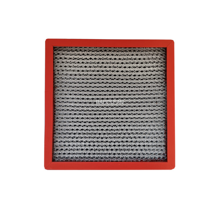
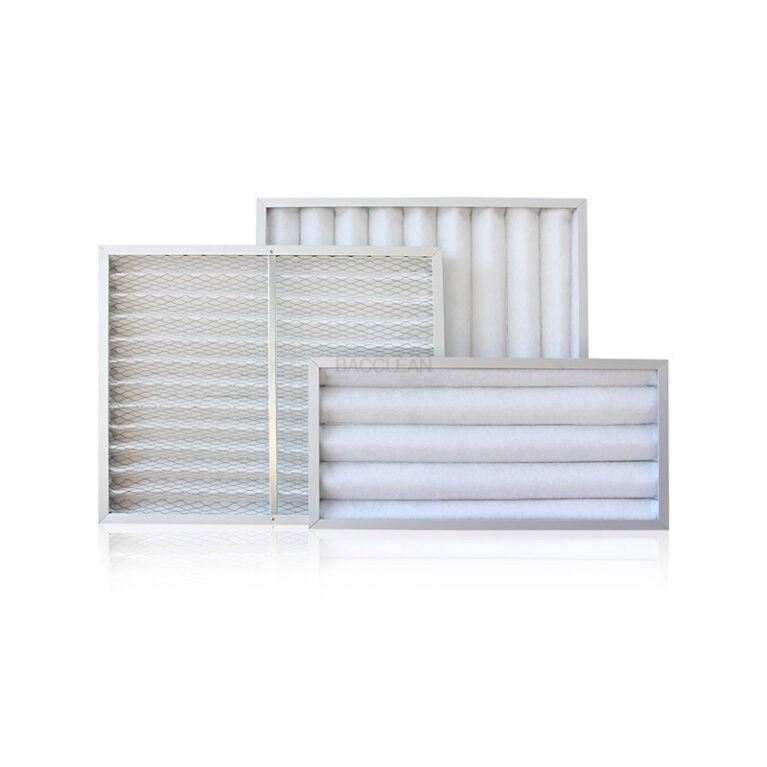
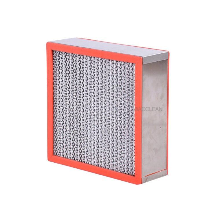
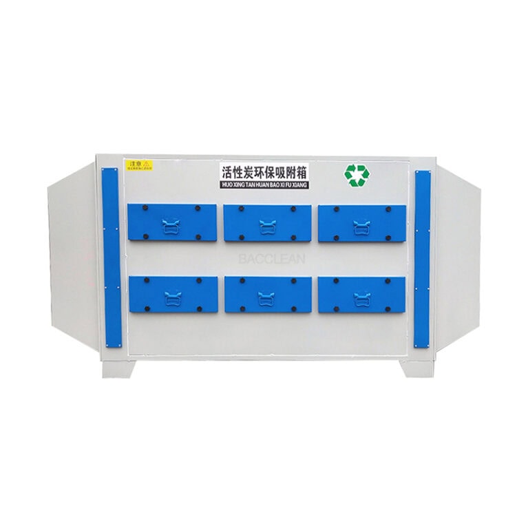
Liquid tank filter inspection: Confirm that the liquid tank seal gel is full, without drying / cracking, the filter frame is tightly sealed with the liquid tank, without gaps; The filter is not damaged or deformed, and is installed properly.
Environmental confirmation: Check that the area cleanliness meets the standards, there is no cross-contamination risk, and irrelevant personnel are evacuated.
Personnel and record preparation
Operators must hold certificates and wear clean clothes, gloves, and masks;
Prepare the leak detection record sheet, clearly indicating the filter number, location, specification, detection date, and instrument number.
2. Upstream dust generation (key points: uniform concentration + stable)
Dusting location selection
The dusting point is set at a distance of ≥ 10 times the duct diameter upstream of the high-efficiency filter to ensure the aerosol is fully mixed with the airflow; If it is a static pressure box, the dusting port is placed in the middle of the box, away from the outlet.
Do not directly dust on the filter material of the filter to avoid excessive local concentration.
Dusting parameter control
Aerosol type: Preferentially use PAO (poly α-olefin, replacing traditional DOP, safer), with a particle size of 0.3 μm as the main type;
Upstream concentration: Control at 10–20 μg/L (the photometer reading should be stable near 100% of the full scale), too low a concentration will result in insufficient sensitivity, and too high a concentration may damage the photometer;
Dusting stability: Continuously dust for ≥ 5 minutes, wait until the fluctuation of the upstream concentration is ≤ ± 5% before starting the downstream scanning.
Upstream concentration verification
Use the photometer probe to detect at the sampling port (or reserved point in the duct) to confirm the concentration is stable, record the values, and use them as the basis for subsequent transmittance calculation.
3. Downstream scanning leak detection (core: full coverage + slow scanning)
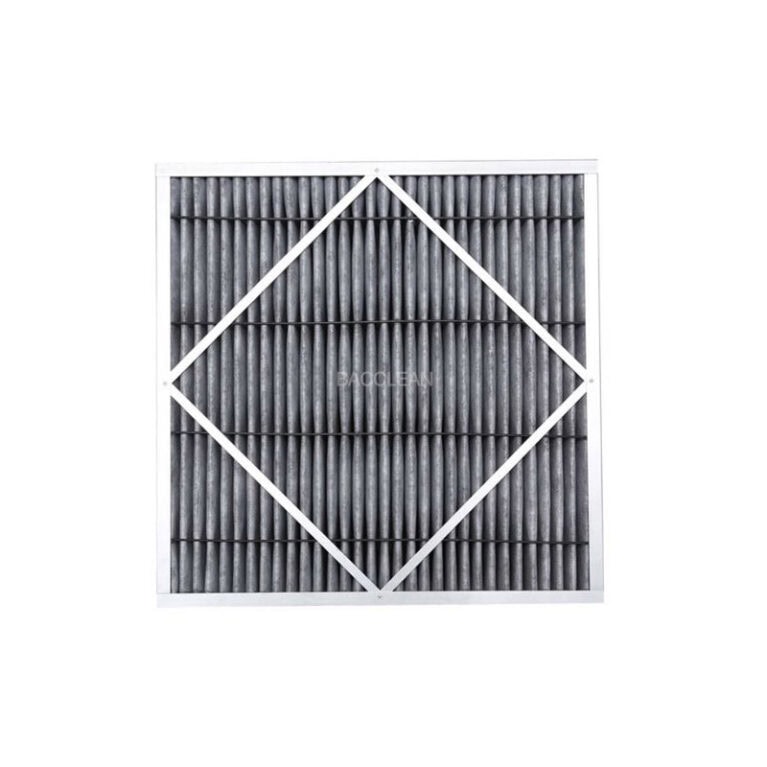
Scan range (no dead zones, with a focus on the liquid tank seal) must cover all possible leakage areas, in sequence: ① The entire surface of the filter material; ② The bonding seams of the filter material and the frame; ③ The sealing surface of the filter frame and the liquid tank (the contact area of the liquid tank gel); ④ The joints between the liquid tank and the static pressure box / enclosure structure; ⑤ The joint seams and screw holes of the filter frame.
Scan operation specifications
Probe distance: The probe should be 25–50mm away from the scanned surface to avoid contact with the filter material / sealing surface and prevent damage;
Scan speed: Move at a constant speed ≤ 5cm/s to ensure the instrument can capture instantaneous leakage;
Scan mode: Use “linear reciprocating mode”, with line overlap ≥ 10mm to avoid missed scanning;
Data reading: Continuously observe the photometer reading and record the maximum transmittance (transmittance = downstream concentration / upstream concentration × 100%) for each area.
Leakage determination and marking
Passing standard: The transmittance of all scanning points should be ≤ 0.01%;
Leakage Marking: If the penetration rate at a certain point is greater than 0.01%, immediately mark the location with a marker pen (such as the middle of the filter material, the sealing area on the left side of the liquid tank), and record the penetration rate value.
IV. Leakage Handling (Key: Compliant Repair + Does Not Affect Sealing)
Based on the classification of the leakage location, handle it in accordance with GMP requirements:
Filter material leakage
Single-point leakage: Use a dedicated high-efficiency filter repair glue / patch (compatible with the filter material), after repair, compact it, without bubbles or wrinkles;
Repair Limitation: The length of single-point repair ≤ 38mm, the cumulative repair area ≤ 3% of the total area of the filter material, if exceeded, replace the filter immediately.
Liquid tank sealing leakage
Gel issue: Add / replace the liquid tank gel to ensure the gel is full and without gaps, and the filter frame is fully embedded in the gel;
Installation issue: Re-adjust the filter position to ensure the frame is evenly adhered to the liquid tank, without warping.
Frame / Joint Leakage
Frame joint: Seal with compliant sealant, after curing, test again;
Static pressure box joint: Reinforce the screws, apply sealant, eliminate the gap.
V. Re-measurement and Final Judgment
Re-measurement after repair
After the repair is completed, restart the dusting (with stable concentration), scan the original leakage point and the surrounding 50mm range, confirm that the penetration rate is ≤ 0.01%;
If still leaking, repeat the repair or replace the filter immediately until qualified.
Overall Re-measurement
After all leakage points of a single filter have been handled, re-scan the entire filter and sealing area, no point with excessive penetration rate, be judged as leak detection qualified.
VI. Report and Archiving (Compliant Retention)
The recorded content should fully include: filter number, installation location, specification model; instrument model, calibration status; upstream concentration, scanning time, maximum penetration rate at each point; leakage location, repair method, re-measurement result; operator and reviewer signatures.
Report Archiving
Issue the “High Efficiency Filter DOP Leak Detection Report”, attach scanning data, leakage photos (if any), and repair records;
The report and instrument calibration records, filter installation records are archived together, with a retention period in line with GMP / industry requirements (usually ≥ 3 years).
Key Precautions
The leakage detection of the liquid tank filter focuses on the sealing surface, not just the filter material, need to focus on scanning the gel contact area;
Do not adjust the system air volume during leakage detection to avoid concentration fluctuations affecting the results;
The repair material should be compatible with the cleanroom environment, without gas release or detachment, in line with GMP clean requirements.